1200 Series IP Video Storage SystemSystem Interface en 7
3System Interface
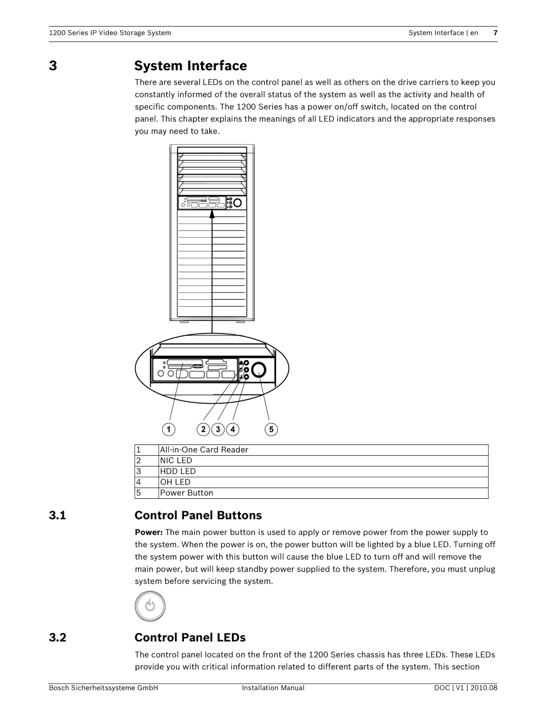
There are several LEDs on the control panel as well as others on the drive carriers to keep you constantly informed of the overall status of the system as well as the activity and health of specific components. The 1200 Series has a power on/off switch, located on the control panel. This chapter explains the meanings of all LED indicators and the appropriate responses you may need to take.
1
2
3
4
5
NIC LED
HDD LED
OH LED
Power Button
3.1Control Panel Buttons
Power: The main power button is used to apply or remove power from the power supply to the system. When the power is on, the power button will be lighted by a blue LED. Turning off the system power with this button will cause the blue LED to turn off and will remove the main power, but will keep standby power supplied to the system. Therefore, you must unplug system before servicing the system.
3.2Control Panel LEDs
The control panel located on the front of the 1200 Series chassis has three LEDs. These LEDs provide you with critical information related to different parts of the system. This section
Bosch Sicherheitssysteme GmbH | Installation Manual | DOC V1 2010.08 |