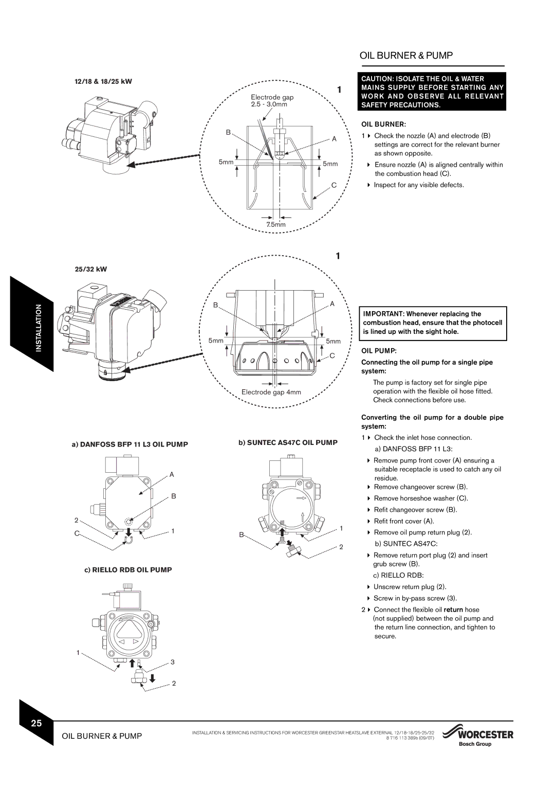
12/18 & 18/25 kW
1
| Electrode gap |
| 2.5 - 3.0mm |
B | A |
| |
5mm | 5mm |
| C |
| 7.5mm |
OIL BURNER & PUMP
CAUTION: ISOLATE THE OIL & WATER MAINS SUPPLY BEFORE STARTING ANY WOR K AN D OB S E RVE ALL R E LE VANT SAFETY PRECAUTIONS.
OIL BURNER:
1Check the nozzle (A) and electrode (B) settings are correct for the relevant burner as shown opposite.
Ensure nozzle (A) is aligned centrally within the combustion head (C).
Inspect for any visible defects.
INSTALLATION
1
25/32 kW
B | A |
5mm | 5mm |
| C |
| Electrode gap 4mm |
a) DANFOSS BFP 11 L3 OIL PUMP | b) SUNTEC AS47C OIL PUMP | ||
| A |
| |
| B |
| |
2 |
| 1 | |
C | 1 | ||
B | |||
| |||
|
| 2 | |
c) RIELLO RDB OIL PUMP
1
3
2
IMPORTANT: Whenever replacing the combustion head, ensure that the photocell is lined up with the sight hole.
OIL PUMP:
Connecting the oil pump for a single pipe system:
The pump is factory set for single pipe operation with the flexible oil hose fitted. Check connections before use.
Converting the oil pump for a double pipe system:
1Check the inlet hose connection.
a)DANFOSS BFP 11 L3:
Remove pump front cover (A) ensuring a suitable receptacle is used to catch any oil residue.
Remove changeover screw (B).
Remove horseshoe washer (C).
Refit changeover screw (B).
Refit front cover (A).
Remove oil pump return plug (2).
b) SUNTEC AS47C:
Remove return port plug (2) and insert grub screw (B).
c)RIELLO RDB: Unscrew return plug (2). Screw in
2Connect the flexible oil return hose (not supplied) between the oil pump and the return line connection, and tighten to secure.
25
OIL BURNER & PUMP
INSTALLATION & SERVICING INSTRUCTIONS FOR WORCESTER GREENSTAR HEATSLAVE EXTERNAL