Bosch Appliances 24I RSF manual Appliance pipework connections

Models: 24I RSF

1 36
Download 36 pages 30.62 Kb
Page 12
Image 12

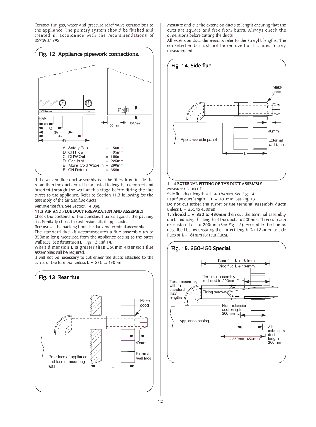
Connect the gas, water and pressure relief valve connections to the appliance. The primary system should be flushed and treated in accordance with the recommendations of BS7593:1992.

Fig. 12. Appliance pipework connections.


(A)


36.5mm


(B)


100mm


(C)


(D)


(E)


(F)


A

Safety Relief

=

50mm


B

CH Flow

=

95mm


C

DHW Out


= 160mm


D

Gas Inlet

=

225mm


E

Mains Cold Water In =

290mm


F

CH Return


= 355mm


If the air and flue duct assembly is to be fitted from inside the room then the ducts must be adjusted to length, assembled and inserted through the wall at this stage before fitting the flue turret to the appliance. Refer to Section 11.3 following for the assembly of the air and flue ducts.

Remove the fan. See Section 14.3(e).

11.3AIR AND FLUE DUCT PREPARATION AND ASSEMBLY

Check the contents of the standard flue kit against the packing list. Similarly check the extension kits if applicable.

Remove all the packing from the flue and terminal assembly. The standard flue kit accommodates a flue assembly up to 350mm long measured from the appliance casing to the outer wall face. See dimension L, Figs.13 and 14.

When dimension L is greater than 350mm extension flue assemblies will be required.

It will not be necessary to cut either the ducts attached to the turret or the terminal unless L = 350 to 450mm.

Fig. 13. Rear flue.

Make good


40mm

Rear face of appliance


External


wall face

and face of mounting


wall


L


Measure and cut the extension ducts to length ensuring that the cuts are square and free from burrs. Always check the dimensions before cutting the ducts.

All extension duct dimensions refer to the straight lengths. The socketed ends must not be removed or included in any measurement.

Fig. 14. Side flue.

Make good


40mm

Appliance side panel


External


wall face


L


11.4EXTERNAL FITTING OF THE DUCT ASSEMBLY Measure distance L.

Side flue duct length = L + 184mm. See Fig. 14. Rear flue duct length = L + 181mm. See Fig. 13.

Do not cut either the turret or the terminal assembly ducts unless L = 350 to 450mm.

1. Should L = 350 to 450mm then cut the terminal assembly ducts reducing the length of the ducts to 200mm. Then cut each extension duct to 200mm (See Fig. 15). Assemble the flue as described below ensuring the correct length (L+184mm for side flues or L+181mm for rear flues).

Fig. 15. 350-450 Special.

Rear flue L + 181mm

Side flue L + 184mm


Terminal assembly


Turret assembly reduced to 200mm


with full


standard

Fixing screws


duct


lengths


Flue extension


duct length


200mm


Appliance casing

Air extension duct

L = 350mm-450mm length 200mm

12

Page 12
Image 12
Bosch Appliances 24I RSF manual Appliance pipework connections, AIR and Flue Duct Preparation and Assembly

24I RSF specifications

Bosch Appliances has long been a leader in the home appliance market, known for its innovation, reliability, and cutting-edge technology. One of the standout products from Bosch is the 24I RSF, a highly regarded model that exemplifies the brand’s commitment to quality and performance in home kitchen solutions.

The Bosch 24I RSF is a high-efficiency dishwasher designed to meet the needs of modern households. It features a sleek, compact design that is perfect for small kitchens or limited spaces without sacrificing capacity and functionality. With its 24-inch width, it seamlessly integrates into most kitchen environments while providing ample space for dishwashing needs.

One of the hallmark features of the Bosch 24I RSF is its incredible water and energy efficiency. Rated among the best in its class, this dishwasher uses sensors to detect how dirty the dishes are, automatically adjusting the wash cycle for optimal performance. This not only conserves water but also reduces energy consumption, making it an environmentally friendly choice for eco-conscious consumers.

The 24I RSF is also equipped with Bosch’s innovative PrecisionWash technology. This advanced system utilizes intelligent sensors to continually scan and adjust the wash cycle, ensuring all dishes are thoroughly cleaned, no matter their placement in the dishwasher. The powerful spray arms reach every corner and crevice, guaranteeing sparkling results every time.

In terms of user convenience, the Bosch 24I RSF comes with flexible loading options, including adjustable racks and a third rack for utensils, allowing users to efficiently optimize space. The Quiet operation, achieving noise levels as low as 44 decibels, makes it perfect for open-concept living spaces. Users can run dishwashing cycles even during quiet moments without disruption.

Another appealing characteristic of the Bosch 24I RSF is its simple user interface with a digital display, offering straightforward selections for the various wash cycles and options tailored to different types of loads. The self-cleaning filter system is an added convenience, reducing the need for maintenance.

Built with quality materials and robust engineering, the Bosch 24I RSF is not only reliable but also stylish, featuring a contemporary design that fits seamlessly into any kitchen decor. The combination of innovation, efficiency, and aesthetic appeal makes the Bosch 24I RSF an attractive choice for homeowners looking to elevate their kitchen experience. Its blend of features ensures exceptional cleaning performance while maintaining a commitment to sustainability, truly embodying the Bosch philosophy of creating appliances that improve everyday life.