Appliance details
Exhaust venting shall be done with 3”
istainless steel
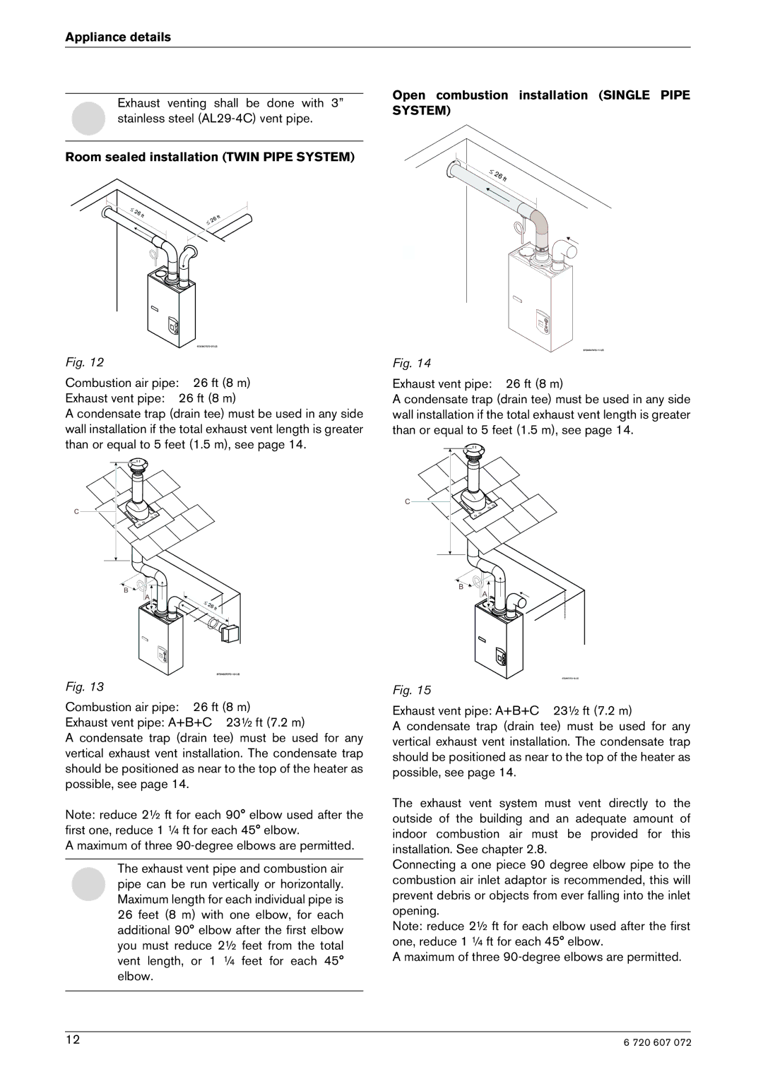
Room sealed installation (TWIN PIPE SYSTEM)
Open combustion installation (SINGLE PIPE SYSTEM)
Fig. 12
Combustion air pipe: ≤ 26 ft (8 m)
Exhaust vent pipe: ≤ 26 ft (8 m)
A condensate trap (drain tee) must be used in any side wall installation if the total exhaust vent length is greater than or equal to 5 feet (1.5 m), see page 14.
Fig. 13
Combustion air pipe: ≤ 26 ft (8 m)
Exhaust vent pipe: A+B+C ≤ 23½ ft (7.2 m)
A condensate trap (drain tee) must be used for any vertical exhaust vent installation. The condensate trap should be positioned as near to the top of the heater as possible, see page 14.
Note: reduce 2½ ft for each 90° elbow used after the first one, reduce 1 ¼ ft for each 45° elbow.
A maximum of three
The exhaust vent pipe and combustion air
ipipe can be run vertically or horizontally. Maximum length for each individual pipe is 26 feet (8 m) with one elbow, for each additional 90° elbow after the first elbow you must reduce 2½ feet from the total vent length, or 1 ¼ feet for each 45° elbow.
Fig. 14
Exhaust vent pipe: ≤ 26 ft (8 m)
A condensate trap (drain tee) must be used in any side wall installation if the total exhaust vent length is greater than or equal to 5 feet (1.5 m), see page 14.
Fig. 15
Exhaust vent pipe: A+B+C ≤ 23½ ft (7.2 m)
A condensate trap (drain tee) must be used for any vertical exhaust vent installation. The condensate trap should be positioned as near to the top of the heater as possible, see page 14.
The exhaust vent system must vent directly to the outside of the building and an adequate amount of indoor combustion air must be provided for this installation. See chapter 2.8.
Connecting a one piece 90 degree elbow pipe to the combustion air inlet adaptor is recommended, this will prevent debris or objects from ever falling into the inlet opening.
Note: reduce 2½ ft for each elbow used after the first one, reduce 1 ¼ ft for each 45° elbow.
A maximum of three
12 | 6 720 607 072 |