DCN Voting Units Installation and User Instructions
en 6
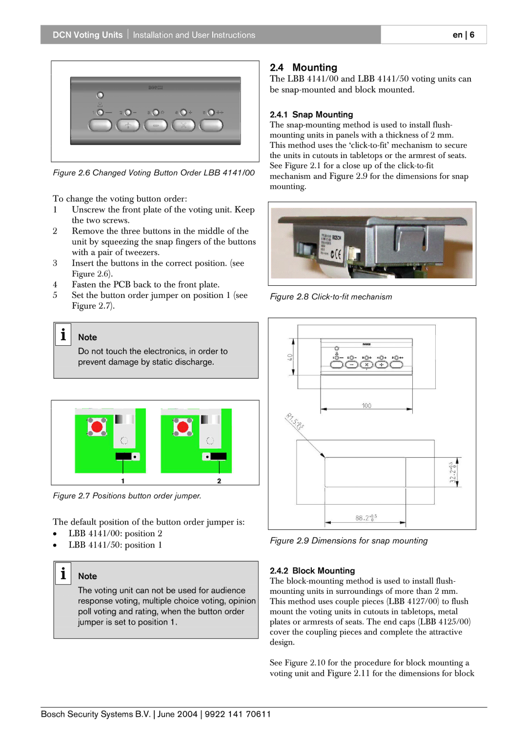
Figure 2.6 Changed Voting Button Order LBB 4141/00
To change the voting button order:
1Unscrew the front plate of the voting unit. Keep the two screws.
2Remove the three buttons in the middle of the unit by squeezing the snap fingers of the buttons with a pair of tweezers.
3Insert the buttons in the correct position. (see
Figure 2.6).
4Fasten the PCB back to the front plate.
5Set the button order jumper on position 1 (see Figure 2.7).
i Note
Do not touch the electronics, in order to prevent damage by static discharge.
![]()
![]() . .
. .![]()
![]()
1 | 2 |
Figure 2.7 Positions button order jumper.
The default position of the button order jumper is:
•LBB 4141/00: position 2
•LBB 4141/50: position 1
i Note
The voting unit can not be used for audience response voting, multiple choice voting, opinion poll voting and rating, when the button order jumper is set to position 1.
2.4 Mounting
The LBB 4141/00 and LBB 4141/50 voting units can be
2.4.1 Snap Mounting
The
Figure 2.8 Click-to-fit mechanism
Figure 2.9 Dimensions for snap mounting
2.4.2 Block Mounting
The
See Figure 2.10 for the procedure for block mounting a voting unit and Figure 2.11 for the dimensions for block