LTC 5104, LTC 5108 Series Instruction Manual Installation | EN 9 |
|
|
4.5Alarm Inputs and Output
(Accessory Output)
A cable with a connector is supplied to connect alarm closures or other accessories to the switcher.
The alarm inputs can be triggered by either a contact closure selectable normally open or closed (e.g., switch or relay) to ground or by a logic ground (e.g., motion detector output).
The alarm output creates a short between the two output pins when an alarm occurs and open circuits the pins when no alarms are active (triggered). The alarm output has a maximum carrying current of 1 A and a maximum switching voltage of 40 V AC/DC. The alarm output can be used to signal a VCR, lamp, or relay.
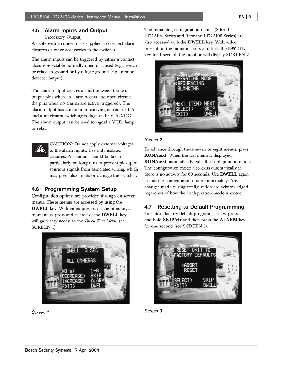
The remaining configuration menus (8 for the
LTC 5104 Series and 9 for the LTC 5108 Series) are also accessed with the DWELL key. With video present on the monitor, press and hold the DWELL key for 1 second; the monitor will display SCREEN 2.
CAUTION: Do not apply external voltages to the alarm inputs. Use only isolated closures. Precautions should be taken particularly on long runs to prevent pickup of spurious signals from associated wiring, which may give false inputs or damage the switcher.
4.6Programming System Setup
Configuration options are provided through
Screen 1
Screen 2
To advance through these seven or eight menus, press RUN/next. When the last menu is displayed, RUN/next automatically exits the configuration mode. The configuration mode also exits automatically if there is no activity for 60 seconds. Use DWELL again to exit the configuration mode immediately. Any changes made during configuration are acknowledged regardless of how the configuration mode is exited.
4.7Resetting to Default Programming
To restore factory default program settings, press and hold SKIP/clr and then press the ALARM key for one second (see SCREEN 3).
Screen 3
Bosch Security Systems 7 April 2004
