Interior components and diagram parts list
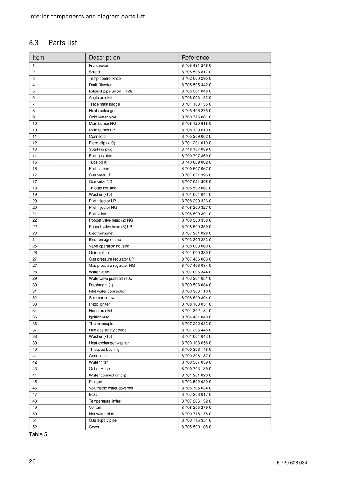
8.3Parts list
Item | Description | Reference |
1 | Front cover | 8 705 431 246 0 |
|
|
|
2 | Shield | 8 705 506 817 0 |
|
|
|
3 | Temp control knob | 8 702 000 295 0 |
|
|
|
4 | Draft Diverter | 8 705 505 442 0 |
|
|
|
5 | Exhaust pipe union Ø128 | 8 705 504 046 0 |
|
|
|
6 | Angle bracket | 8 708 003 192 0 |
|
|
|
7 | Trade mark badge | 8 701 103 135 0 |
|
|
|
8 | Heat exchanger | 8 705 406 275 0 |
|
|
|
9 | Cold water pipe | 8 700 715 061 0 |
|
|
|
10 | Main burner NG | 8 708 120 618 0 |
|
|
|
10 | Main burner LP | 8 708 120 619 0 |
|
|
|
11 | Connector | 8 705 209 062 0 |
|
|
|
12 | Piezo clip (x10) | 8 701 201 019 0 |
|
|
|
13 | Sparking plug | 8 748 107 089 0 |
|
|
|
14 | Pilot gas pipe | 8 700 707 369 0 |
|
|
|
15 | Tube (x10) | 8 740 609 002 0 |
|
|
|
16 | Pilot screen | 8 700 507 067 0 |
|
|
|
17 | Gas valve LP | 8 707 021 396 0 |
|
|
|
17 | Gas valve NG | 8 707 021 395 0 |
|
|
|
18 | Throttle housing | 8 705 502 067 0 |
|
|
|
19 | Washer (x10) | 8 701 004 044 0 |
|
|
|
20 | Pilot injector LP | 8 708 200 326 0 |
|
|
|
20 | Pilot injector NG | 8 708 200 327 0 |
|
|
|
21 | Pilot valve | 8 708 500 301 0 |
|
|
|
22 | Poppet valve head (2) NG | 8 708 500 358 0 |
|
|
|
22 | Poppet valve head (3) LP | 8 708 500 359 0 |
|
|
|
23 | Electromagnet | 8 707 201 028 0 |
|
|
|
24 | Electromagnet cap | 8 703 305 283 0 |
|
|
|
25 | Valve operation housing | 8 708 008 069 0 |
|
|
|
26 | Guide plate | 8 701 000 380 0 |
|
|
|
27 | Gas pressure regulator LP | 8 707 406 083 0 |
|
|
|
27 | Gas pressure regulator NG | 8 707 406 084 0 |
|
|
|
28 | Water valve | 8 707 006 344 0 |
|
|
|
29 | Watervalve pushrod (10x) | 8 703 204 051 0 |
|
|
|
30 | Diaphragm (L) | 8 700 503 084 0 |
|
|
|
31 | Inlet water connection | 8 700 306 110 0 |
|
|
|
32 | Selector screw | 8 708 500 304 0 |
|
|
|
33 | Piezo igniter | 8 708 108 051 0 |
|
|
|
34 | Fixing bracket | 8 701 302 181 0 |
|
|
|
35 | Ignition lead | 8 704 401 040 0 |
|
|
|
36 | Thermocouple | 8 707 202 083 0 |
|
|
|
37 | Flue gas safety device | 8 707 206 445 0 |
|
|
|
38 | Washer (x10) | 8 701 004 043 0 |
|
|
|
39 | Heat exchanger washer | 8 700 103 658 0 |
|
|
|
40 | Threaded bushing | 8 700 306 148 0 |
|
|
|
41 | Connector | 8 700 306 187 0 |
|
|
|
42 | Water filter | 8 700 507 059 0 |
|
|
|
43 | Outlet Hose | 8 700 703 139 0 |
|
|
|
44 | Water connection clip | 8 701 201 020 0 |
|
|
|
45 | Plunger | 8 703 502 039 0 |
|
|
|
46 | Volumetric water governor | 8 705 705 034 0 |
|
|
|
47 | ECO | 8 707 206 017 0 |
|
|
|
48 | Temperature limiter | 8 707 206 132 0 |
|
|
|
49 | Venturi | 8 708 205 279 0 |
|
|
|
50 | Hot water pipe | 8 700 715 178 0 |
|
|
|
51 | Gas supply pipe | 8 700 715 351 0 |
|
|
|
52 | Cover | 8 705 500 105 0 |
|
|
|
Table 5
26 | 6 720 608 034 |
