Installation instructions
3.7 Gas piping & connections
Before connecting the gas supply, check the rating plate on the right side of the heater to be sure that the heater is rated for the same gas to which it will be connected.
In the United States: The installation must conform with local codes or, in the absence of local codes, the National Fuel Gas Code ANSI Z223.1/NFPA 54.
In Canada: The Installation should conform to CGA B149 INSTALLATION CODES and/or local installation codes.
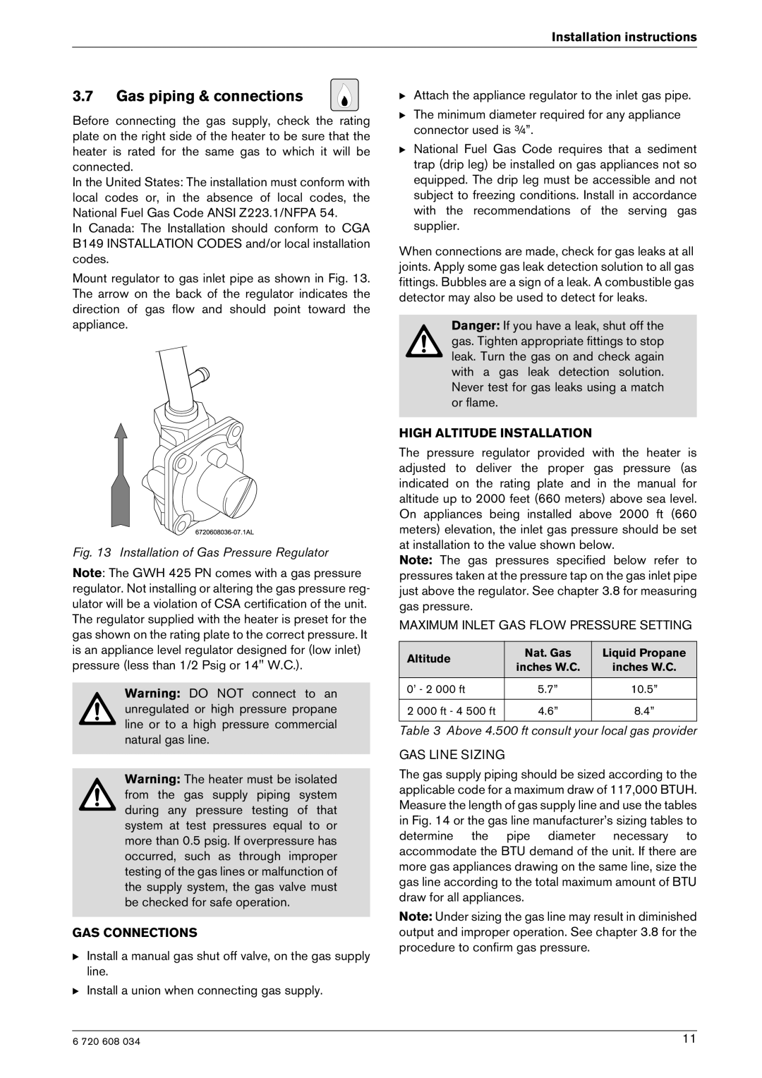
Mount regulator to gas inlet pipe as shown in Fig. 13. The arrow on the back of the regulator indicates the direction of gas flow and should point toward the appliance.
Fig. 13 Installation of Gas Pressure Regulator
Note: The GWH 425 PN comes with a gas pressure regulator. Not installing or altering the gas pressure reg- ulator will be a violation of CSA certification of the unit. The regulator supplied with the heater is preset for the gas shown on the rating plate to the correct pressure. It is an appliance level regulator designed for (low inlet) pressure (less than 1/2 Psig or 14" W.C.).
Warning: DO NOT connect to an unregulated or high pressure propane line or to a high pressure commercial natural gas line.
Warning: The heater must be isolated from the gas supply piping system during any pressure testing of that system at test pressures equal to or more than 0.5 psig. If overpressure has occurred, such as through improper testing of the gas lines or malfunction of the supply system, the gas valve must be checked for safe operation.
GAS CONNECTIONS
BInstall a manual gas shut off valve, on the gas supply line.
BInstall a union when connecting gas supply.
BAttach the appliance regulator to the inlet gas pipe.
BThe minimum diameter required for any appliance connector used is ¾”.
BNational Fuel Gas Code requires that a sediment trap (drip leg) be installed on gas appliances not so equipped. The drip leg must be accessible and not subject to freezing conditions. Install in accordance with the recommendations of the serving gas supplier.
When connections are made, check for gas leaks at all joints. Apply some gas leak detection solution to all gas fittings. Bubbles are a sign of a leak. A combustible gas detector may also be used to detect for leaks.
Danger: If you have a leak, shut off the gas. Tighten appropriate fittings to stop leak. Turn the gas on and check again with a gas leak detection solution. Never test for gas leaks using a match or flame.
HIGH ALTITUDE INSTALLATION
The pressure regulator provided with the heater is adjusted to deliver the proper gas pressure (as indicated on the rating plate and in the manual for altitude up to 2000 feet (660 meters) above sea level. On appliances being installed above 2000 ft (660 meters) elevation, the inlet gas pressure should be set at installation to the value shown below.
Note: The gas pressures specified below refer to pressures taken at the pressure tap on the gas inlet pipe just above the regulator. See chapter 3.8 for measuring gas pressure.
MAXIMUM INLET GAS FLOW PRESSURE SETTING
Altitude | Nat. Gas | Liquid Propane | |
inches W.C. | inches W.C. | ||
| |||
0’ - 2 000 ft | 5.7” | 10.5” | |
|
|
| |
2 000 ft - 4 500 ft | 4.6” | 8.4” | |
|
|
|
Table 3 Above 4.500 ft consult your local gas provider
GAS LINE SIZING
The gas supply piping should be sized according to the applicable code for a maximum draw of 117,000 BTUH. Measure the length of gas supply line and use the tables in Fig. 14 or the gas line manufacturer’s sizing tables to determine the pipe diameter necessary to accommodate the BTU demand of the unit. If there are more gas appliances drawing on the same line, size the gas line according to the total maximum amount of BTU draw for all appliances.
Note: Under sizing the gas line may result in diminished output and improper operation. See chapter 3.8 for the procedure to confirm gas pressure.
6 720 608 034 | 11 |