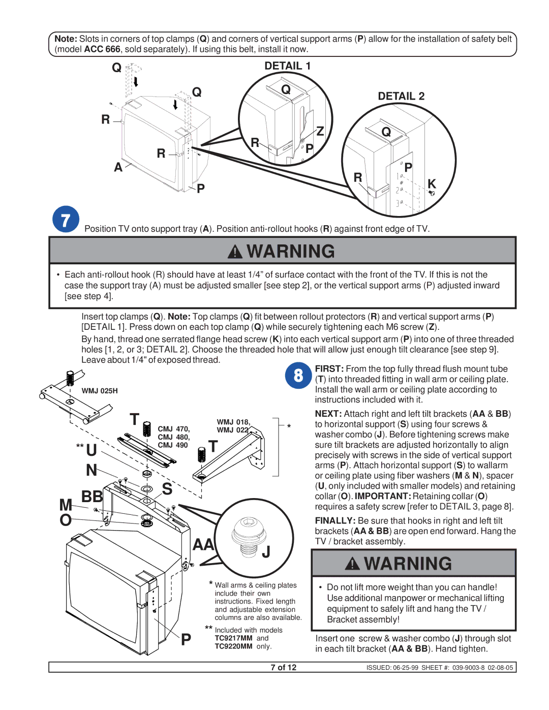
Note: Slots in corners of top clamps (Q) and corners of vertical support arms (P) allow for the installation of safety belt (model ACC 666, sold separately). If using this belt, install it now.
Q |
| DETAIL 1 |
|
|
Q |
| Q |
| DETAIL 2 |
R |
| Z |
| Q |
| R |
| ||
R | P |
|
| |
|
|
| ||
|
|
|
| |
A |
|
| R | P |
P |
|
| K | |
|
|
| ||
|
|
|
|
![]() Position TV onto support tray (A). Position
Position TV onto support tray (A). Position
![]() WARNING
WARNING
•Each
Insert top clamps (Q). Note: Top clamps (Q) fit between rollout protectors (R) and vertical support arms (P) [DETAIL 1]. Press down on each top clamp (Q) while securely tightening each M6 screw (Z).
By hand, thread one serrated flange head screw (K) into each vertical support arm (P) into one of three threaded holes [1, 2, or 3; DETAIL 2]. Choose the threaded hole that will allow just enough tilt clearance [see step 9]. Leave about 1/4" of exposed thread.
|
|
|
|
| FIRST: From the top fully thread flush mount tube |
|
|
|
|
| (T) into threaded fitting in wall arm or ceiling plate. |
WMJ 025H |
|
|
|
| Install the wall arm or ceiling plate according to |
|
|
|
|
| instructions included with it. |
| T |
| WMJ 018, |
| NEXT: Attach right and left tilt brackets (AA & BB) |
|
| * | to horizontal support (S) using four screws & | ||
| CMJ 470, |
| WMJ 022 | washer combo (J). Before tightening screws make | |
| CMJ 480, | T |
| ||
** U | CMJ 490 |
| sure tilt brackets are adjusted horizontally to align | ||
|
| precisely with screws in the side of vertical support | |||
N |
|
|
|
| arms (P). Attach horizontal support (S) to wallarm |
S |
|
|
| or ceiling plate using fiber washers (M & N), spacer | |
M BB |
|
|
| (U, only included with smaller models) and retaining | |
|
|
| collar (O). IMPORTANT: Retaining collar (O) | ||
|
|
|
| requires a safety screw [refer to DETAIL 3, page 8]. | |
O |
|
|
|
| FINALLY: Be sure that hooks in right and left tilt |
|
| AA |
|
| brackets (AA & BB) are open end forward. Hang the |
|
| J |
| TV / bracket assembly. | |
|
|
|
| ||
|
|
|
| WARNING | |
|
|
|
|
| |
|
| * Wall arms & ceiling plates | • Do not lift more weight than you can handle! | ||
|
|
| include their own |
| Use additional manpower or mechanical lifting |
|
|
| instructions. Fixed length | ||
|
|
| and adjustable extension | equipment to safely lift and hang the TV / | |
|
|
| columns are also available. | Bracket assembly! | |
| P | ** Included with models |
| Insert one screw & washer combo (J) through slot | |
|
| TC9217MM and |
| ||
|
| TC9220MM only. |
| in each tilt bracket (AA & BB). Hand tighten. | |
|
|
|
|
| |
7 of 12 | ISSUED: |