16 en Installing the MonitorGeneral Purpose LCD Monitors
6.4Connecting the Y/C (S-Video) Signal to the Monitor
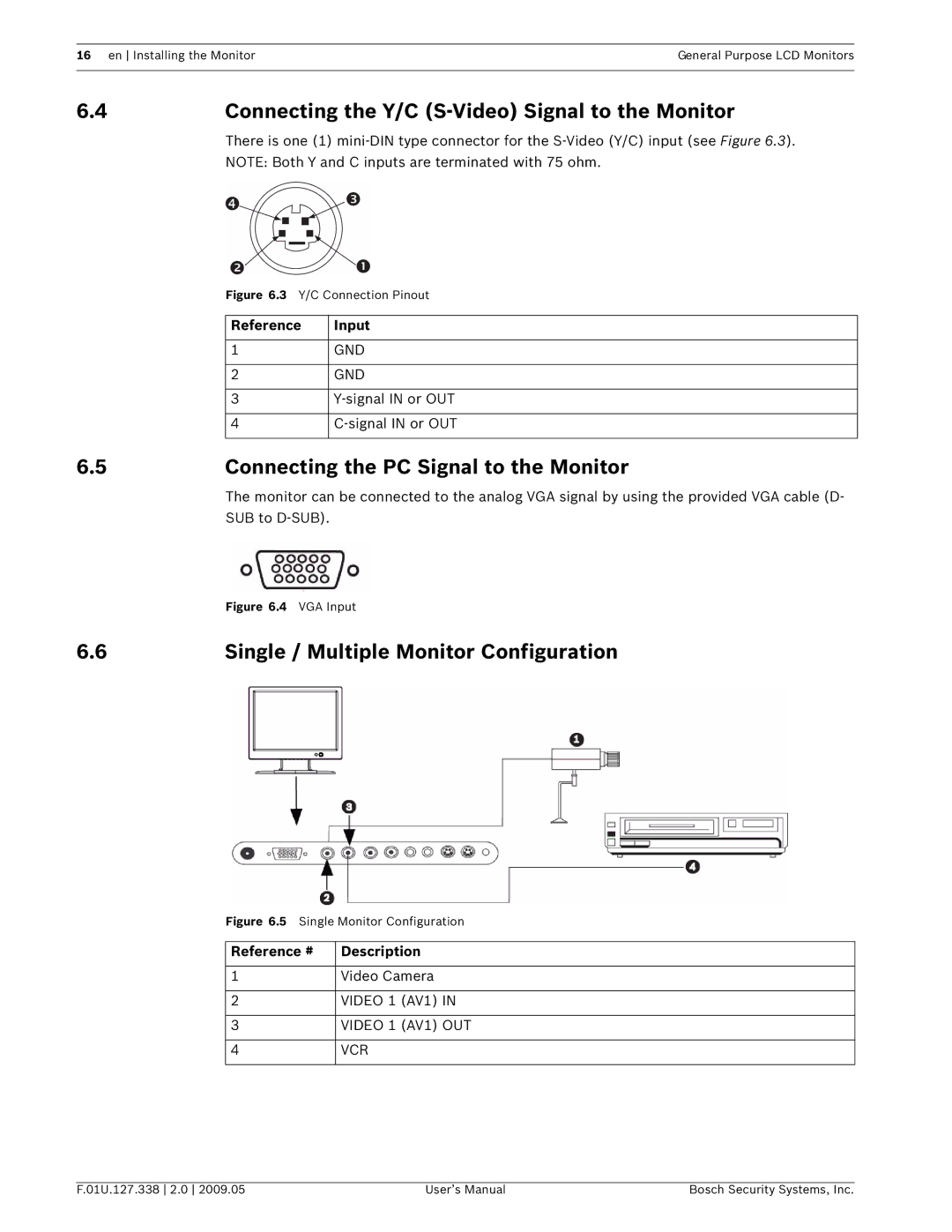
There is one (1)
NOTE: Both Y and C inputs are terminated with 75 ohm.
Figure 6.3 Y/C Connection Pinout | |
|
|
Reference | Input |
|
|
1 | GND |
|
|
2 | GND |
|
|
3 | |
|
|
4 | |
|
|
6.5Connecting the PC Signal to the Monitor
The monitor can be connected to the analog VGA signal by using the provided VGA cable (D- SUB to
| Figure 6.4 VGA Input |
6.6 | Single / Multiple Monitor Configuration |
Figure 6.5 Single Monitor Configuration
Reference # | Description | |
|
| |
1 | Video Camera | |
|
|
|
2 | VIDEO 1 | (AV1) IN |
|
|
|
3 | VIDEO 1 | (AV1) OUT |
|
|
|
4 | VCR |
|
|
|
|
F.01U.127.338 2.0 2009.05 | User’s Manual | Bosch Security Systems, Inc. |