BM 2609932519
BRAKE
When the trigger switch is released it activates the brake to stop the chuck quickly. This is especially useful in the repetitive driving and removal of screws.
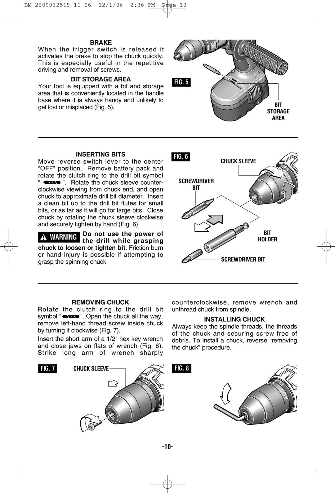
BIT STORAGE AREA |
| |
FIG. 5 | ||
Your tool is equipped with a bit and storage | ||
| ||
area that is conveniently located in the handle |
| |
base where it is always handy and unlikely to |
| |
get lost or misplaced (Fig. 5). |
|
BIT
STORAGE
AREA
INSERTING BITS
Move reverse switch lever to the center “OFF” position. Remove battery pack and rotate the clutch ring to the drill bit symbol
“![]()
![]() ”. Rotate the chuck sleeve counter- clockwise viewing from chuck end, and open chuck to approximate drill bit diameter. Insert a clean bit up to the drill bit flutes for small bits, or as far as it will go for large bits. Close chuck by rotating the chuck sleeve clockwise and securely tighten by hand (Fig. 6).
”. Rotate the chuck sleeve counter- clockwise viewing from chuck end, and open chuck to approximate drill bit diameter. Insert a clean bit up to the drill bit flutes for small bits, or as far as it will go for large bits. Close chuck by rotating the chuck sleeve clockwise and securely tighten by hand (Fig. 6).
!WARNING Do not use the power of the drill while grasping
chuck to loosen or tighten bit. Friction burn or hand injury is possible if attempting to grasp the spinning chuck.
FIG. 6
CHUCK SLEEVE
SCREWDRIVER
BIT
BIT
HOLDER
![]()
![]() SCREWDRIVER BIT
SCREWDRIVER BIT
REMOVING CHUCK
Rotate the clutch ring to the drill bit
symbol “ ![]()
![]() ”. Open the chuck all the way, remove
”. Open the chuck all the way, remove
Insert the short arm of a 1/2" hex key wrench and close jaws on flats of wrench (Fig. 8). Strike long arm of wrench sharply
FIG. 7 | E |
|
|
|
CHUCK SLEEVE |
|
|
| |
|
|
| ||
|
|
|
|
|
counterclockwise, remove wrench and unthread chuck from spindle.
INSTALLING CHUCK
Always keep the spindle threads, the threads of the chuck and securing screw free of debris. To install a chuck, reverse “removing the chuck” procedure.
FIG. 8