INSTRUCTIONS
24.WIRING DIAGRAM
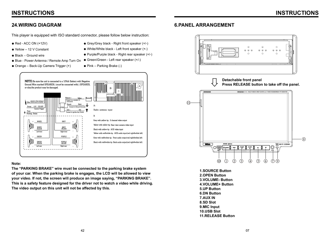
This player is equipped with ISO standard connector, please follow below instruction:
INSTRUCTIONS
6.PANEL ARRANGEMENT
●Red - ACC ON (+12V)
●Yellow – 12 V Constant
●Black – Ground wire
●Blue - Power Antenna / Remote Amp Turn On
●Orange –
●Grey/Grey black - Right front speaker
●White/White black - Left front speaker
●Purple/Purple black - Right rear speaker
●Green/Green - Left rear speaker
●Pink – Parking Brake
Detachable front panel
Press RELEASE button to take off the panel.
Note:
The “PARKING BRAKE” wire must be connected to the parking brake system of your car. When the parking brake is engages, the LCD will be allowed to view your video. If not, the screen will produce an image saying, “PARKING BRAKE”. This is a safety feature designed for the driver not to watch a video while driving. The video output on this unit will not be affected by this.
1.SOURCE Button 2.OPEN Button 3.VOLUME- Button 4.VOLUME+ Button 5.UP Button
6.DN Button 7.AUX IN 8.SD Slot 9.MIC Input 10.USB Slot 11.RELEASE Button