Speaker Installation Locations
When selecting installation locations you must take into account both mechanical and acoustical factors. The pivoting tweeter of the PRi665 and PRi685 helps them produce excellent sound even when they are installed in less than ideal locations.
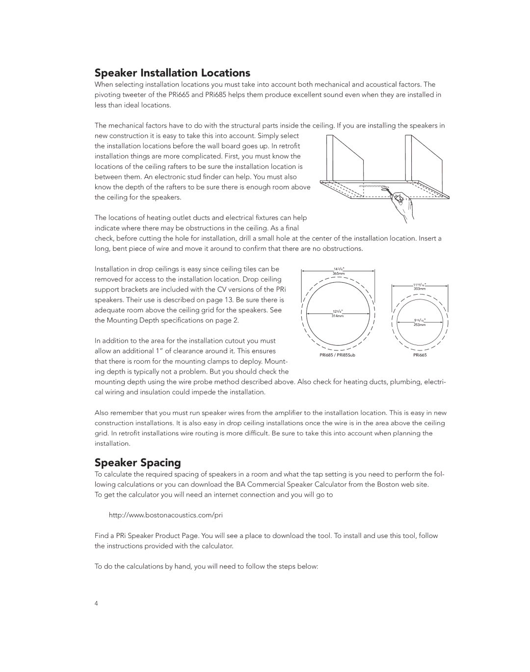
The mechanical factors have to do with the structural parts inside the ceiling. If you are installing the speakers in new construction it is easy to take this into account. Simply select
the installation locations before the wall board goes up. In retrofit installation things are more complicated. First, you must know the locations of the ceiling rafters to be sure the installation location is between them. An electronic stud finder can help. You must also
know the depth of the rafters to be sure there is enough room above the ceiling for the speakers.
The locations of heating outlet ducts and electrical fixtures can help indicate where there may be obstructions in the ceiling. As a final
check, before cutting the hole for installation, drill a small hole at the center of the installation location. Insert a long, bent piece of wire and move it around to confirm that there are no obstructions.
Installation in drop ceilings is easy since ceiling tiles can be |
|
|
| Ê | £{ÎÉn | ¸ |
|
|
|
|
|
|
|
|
|
| |
|
|
|
|
|
|
|
|
|
|
|
| ||||||
removed for access to the installation location. Drop ceiling |
|
|
| ÎÈx |
|
|
|
|
|
|
|
| |||||
|
|
|
|
|
|
|
|
|
|
|
| £££xɣȸ |
| ||||
support brackets are included with the CV versions of the PRi |
|
|
|
|
|
|
|
|
|
|
|
|
|
| |||
|
|
|
|
|
|
|
|
|
|
|
| ÎäÎ |
| ||||
|
|
|
|
|
|
|
|
|
|
|
|
|
|
|
| ||
speakers. Their use is described on page 13. Be sure there is |
|
|
|
|
|
|
|
|
|
|
|
|
|
|
|
| |
adequate room above the ceiling grid for the speakers. See | Ê£ÓÎÉn¸ |
|
|
|
|
|
|
| |||||||||
|
|
|
|
|
| ||||||||||||
|
|
|
|
|
|
|
|
|
|
|
|
|
|
|
|
|
|
the Mounting Depth specifications on page 2. | Î | £{ |
|
|
|
|
|
|
|
| £xÉ£È | ¸ |
| ||||
|
|
|
|
|
|
|
|
| Ê |
| |||||||
|
|
|
|
|
|
|
|
|
|
|
|
|
| ÓxÎ |
| ||
In addition to the area for the installation cutout you must |
|
|
|
|
|
|
|
|
|
|
|
|
|
| |||
allow an additional 1” of clearance around it. This ensures |
| *,ÈÈx |
| ||||||||||||||
that there is room for the mounting clamps to deploy. Mount- |
|
| |||||||||||||||
|
|
|
|
|
|
|
|
|
|
|
|
|
| ||||
ing depth is typically not a problem. But you should check the |
|
|
|
|
|
|
|
|
|
|
|
|
|
| |||
mounting depth using the wire probe method described above. Also check for heating ducts, plumbing, electri- cal wiring and insulation could impede the installation.
Also remember that you must run speaker wires from the amplifier to the installation location. This is easy in new construction installations. It is also easy in drop ceiling installations once the wire is in the area above the ceiling grid. In retrofit installations wire routing is more difficult. Be sure to take this into account when planning the installation.
Speaker Spacing
To calculate the required spacing of speakers in a room and what the tap setting is you need to perform the fol- lowing calculations or you can download the BA Commercial Speaker Calculator from the Boston web site.
To get the calculator you will need an internet connection and you will go to
http://www.bostonacoustics.com/pri
Find a PRi Speaker Product Page. You will see a place to download the tool. To install and use this tool, follow the instructions provided with the calculator.
To do the calculations by hand, you will need to follow the steps below:
