![]() = 1x
= 1x
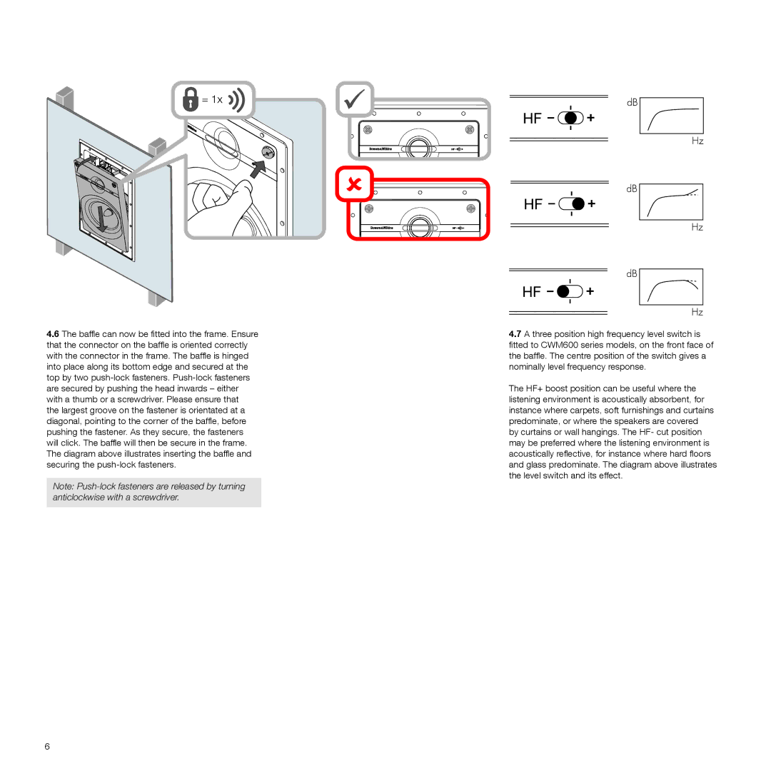
4.6The baffle can now be fitted into the frame. Ensure that the connector on the baffle is oriented correctly with the connector in the frame. The baffle is hinged into place along its bottom edge and secured at the top by two
Note:
6
4.7A three position high frequency level switch is fitted to CWM600 series models, on the front face of the baffle. The centre position of the switch gives a nominally level frequency response.
The HF+ boost position can be useful where the listening environment is acoustically absorbent, for instance where carpets, soft furnishings and curtains predominate, or where the speakers are covered by curtains or wall hangings. The HF- cut position may be preferred where the listening environment is acoustically reflective, for instance where hard floors and glass predominate. The diagram above illustrates the level switch and its effect.