Assembly Instructions
To ensure ease of assembly please verify the size and quantity of all the required assembly hardware and parts with the enclosed parts list and hardware chart.
The assembly process has been broken down into 5
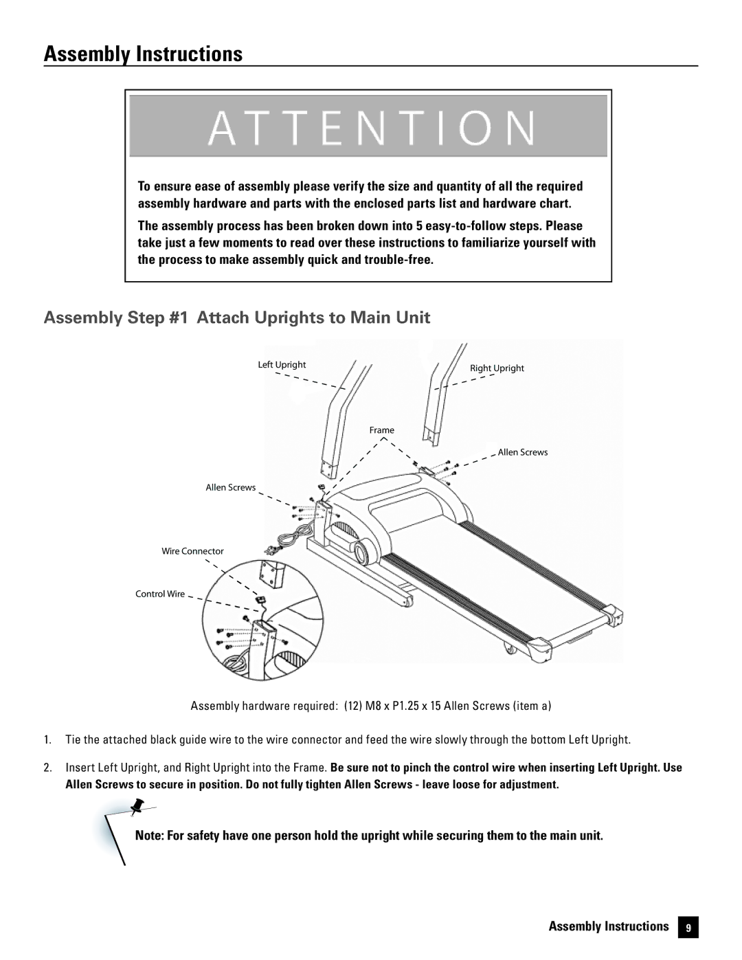
assembly step #1 attach uprights to main unit
Left Upright | Right Upright |
|
Frame
Allen Screws
Allen Screws
Wire Connector
Control Wire
Assembly hardware required: (12) M8 x P1.25 x 15 Allen Screws (item a)
1 . Tie the attached black guide wire to the wire connector and feed the wire slowly through the bottom Left Upright .
2 . Insert Left Upright, and Right Upright into the Frame . Be sure not to pinch the control wire when inserting Left Upright. Use
Allen Screws to secure in position. Do not fully tighten Allen Screws - leave loose for adjustment.
Note: For safety have one person hold the upright while securing them to the main unit.
Assembly Instructions 9