Internet Version for Reference Only | BRADFORD WHITE |
Page 14 |
SECTION 3.
Operation
3.1 Controls - General
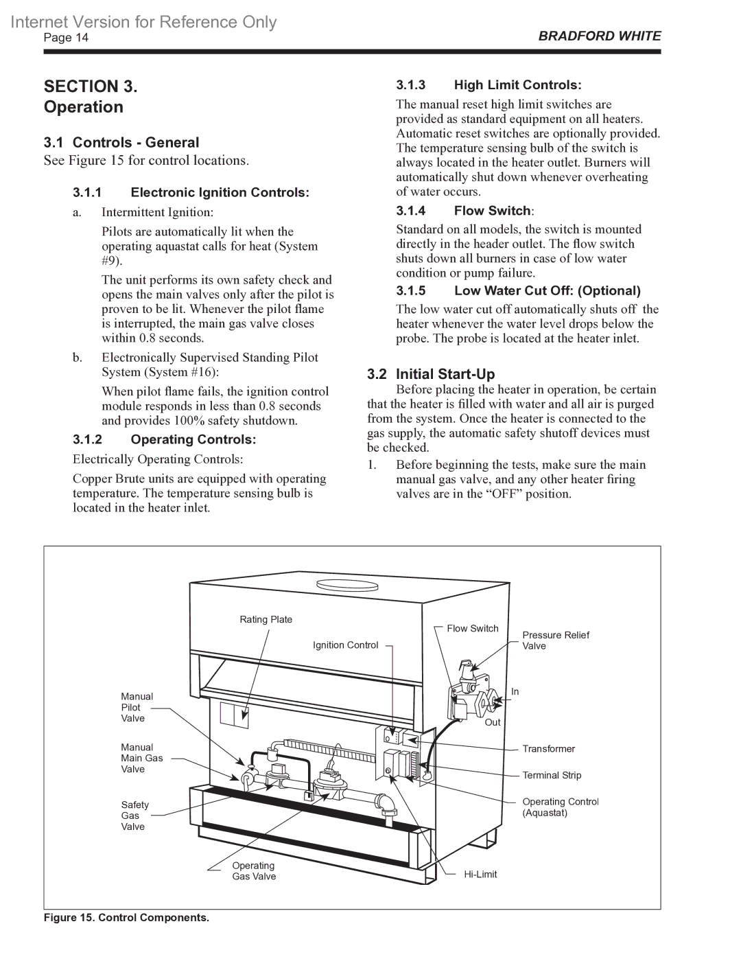
See Figure 15 for control locations.
3.1.1Electronic Ignition Controls:
a.Intermittent Ignition:
3.1.3High Limit Controls:
The manual reset high limit switches are provided as standard equipment on all heaters. Automatic reset switches are optionally provided. The temperature sensing bulb of the switch is always located in the heater outlet. Burners will automatically shut down whenever overheating of water occurs.
3.1.4Flow Switch:
Pilots are automatically lit when the operating aquastat calls for heat (System #9).
The unit performs its own safety check and opens the main valves only after the pilot is proven to be lit. Whenever the pilot flame is interrupted, the main gas valve closes within 0.8 seconds.
b.Electronically Supervised Standing Pilot System (System #16):
When pilot flame fails, the ignition control module responds in less than 0.8 seconds and provides 100% safety shutdown.
3.1.2Operating Controls:
Electrically Operating Controls:
Copper Brute units are equipped with operating temperature. The temperature sensing bulb is located in the heater inlet.
Standard on all models, the switch is mounted directly in the header outlet. The flow switch shuts down all burners in case of low water condition or pump failure.
3.1.5Low Water Cut Off: (Optional)
The low water cut off automatically shuts off the heater whenever the water level drops below the probe. The probe is located at the heater inlet.
3.2Initial Start-Up
Before placing the heater in operation, be certain
that the heater is filled with water and all air is purged from the system. Once the heater is connected to the gas supply, the automatic safety shutoff devices must be checked.
1.Before beginning the tests, make sure the main manual gas valve, and any other heater firing valves are in the “OFF” position.
Rating Plate | Flow Switch |
|
| Pressure Relief | |
Ignition Control |
| |
| Valve | |
Manual |
| In |
|
| |
Pilot |
|
|
Valve | Out |
|
|
| |
Manual |
| Transformer |
Main Gas |
|
|
Valve |
| Terminal Strip |
|
| |
Safety |
| Operating Control |
Gas |
| (Aquastat) |
Valve |
|
|
Operating |
| |
Gas Valve |
|