500-1825 specifications
Bradford-White Corporation is renowned for manufacturing high-quality water heating solutions, and the model 500-1825 is a prime example of the company's commitment to innovation and durability. This water heater is particularly well-suited for residential and commercial applications, providing users with efficient and reliable hot water.One of the key features of the Bradford-White 500-1825 is its robust construction. Built with high-quality materials, it boasts a glass-lined tank that ensures maximum protection against corrosion. This feature extends the lifespan of the unit significantly, providing users with a long-lasting solution for their hot water needs. The tank's insulation is designed to minimize heat loss, thereby enhancing the unit's energy efficiency and lowering operating costs.
The 500-1825 model employs advanced heating technologies that facilitate rapid heating and recovery rates. It is equipped with a powerful burner system that ensures a quick restoration of hot water even during peak usage times. This feature is particularly beneficial for larger households and commercial environments where hot water demand can be substantial.
Another standout characteristic of the Bradford-White 500-1825 is its user-friendly controls. The model typically includes a smart thermostat that allows users to precisely set and maintain their desired water temperature. This functionality not only enhances comfort but also contributes to energy savings, as the system operates according to the specific needs of the user.
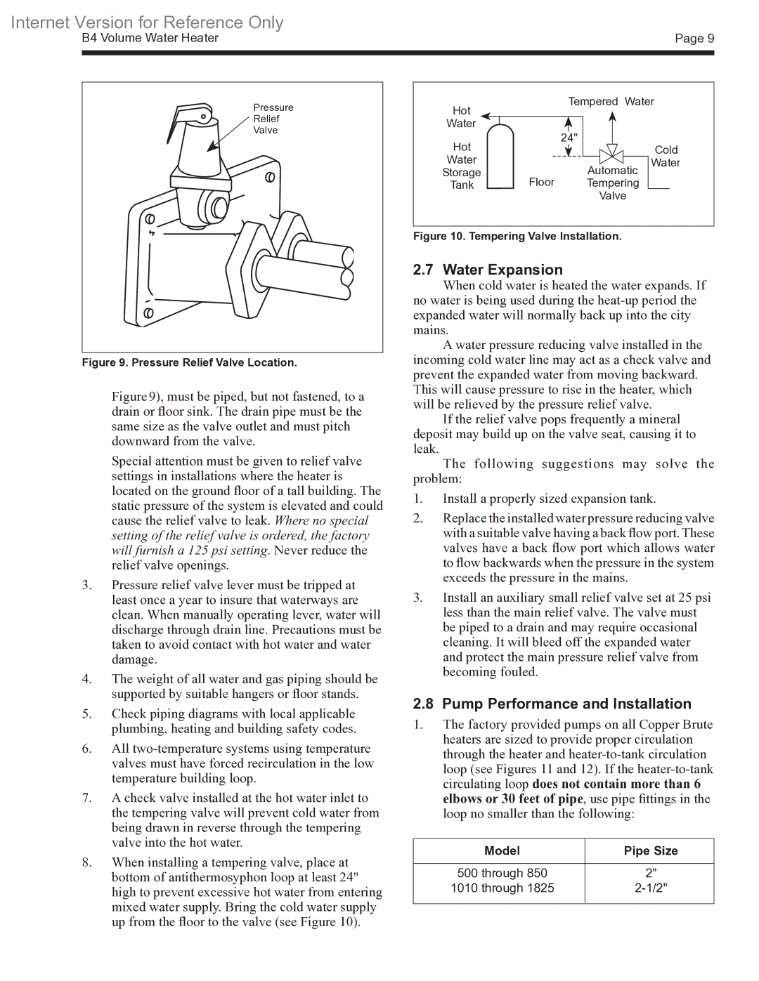
Safety features are paramount in the design of the 500-1825. The unit often includes multiple safety mechanisms, such as a combination temperature and pressure relief valve. This ensures that the water heater operates within safe parameters, providing peace of mind for homeowners and businesses alike.
Additionally, Bradford-White's commitment to innovation is evident in their focus on sustainability. The 500-1825 is designed to meet or exceed stringent energy efficiency standards. This means that users can enjoy the benefits of significant energy savings while reducing their environmental footprint.
In conclusion, the Bradford-White 500-1825 water heater exemplifies the company's dedication to quality, efficiency, and safety. With its durable construction, advanced heating technologies, user-friendly controls, and emphasis on sustainability, it stands out as a reliable choice for those in need of effective hot water solutions. Whether for residential use or commercial applications, the 500-1825 continues to be a trusted option among consumers.

