Floor Level and Inner Roll Stop Adjustments
Inner Roll Stop Adjustment
Do not ad- just the in- ner roll stop linkage rod unless extra usable plat- form length is needed. See Photo
G.If the angle of the inner roll stop (when in the vertical position) restricts the usable platform length for the wheelchair pas- senger, adjustment of the linkage rod will change the angle.
Adjust the inner roll stop as detailed in the previous procedures. Then, adjust the link- age rod as detailed (only if necessary). If the linkage rod is adjusted too long or too short, it will exceed the travel of the slider block resulting in damage to the cam fol- lower bearing, the cam and/or other compo- nents.
1.Position the lift platform below stow level using the manual operation system. Do not operate the lift with the electric pump during adjustment procedures.
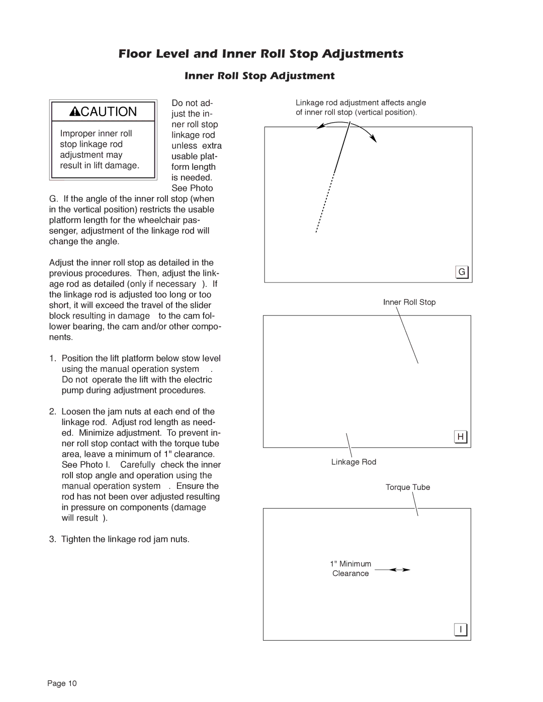
2.Loosen the jam nuts at each end of the linkage rod. Adjust rod length as need- ed. Minimize adjustment. To prevent in- ner roll stop contact with the torque tube area, leave a minimum of 1" clearance. See Photo I. Carefully check the inner roll stop angle and operation using the manual operation system. Ensure the rod has not been over adjusted resulting in pressure on components (damage will result).
3.Tighten the linkage rod jam nuts.
Linkage rod adjustment affects angle of inner roll stop (vertical position).
G |
Inner Roll Stop
H |
Linkage Rod
Torque Tube
1" Minimum
Clearance
I |
Page 10