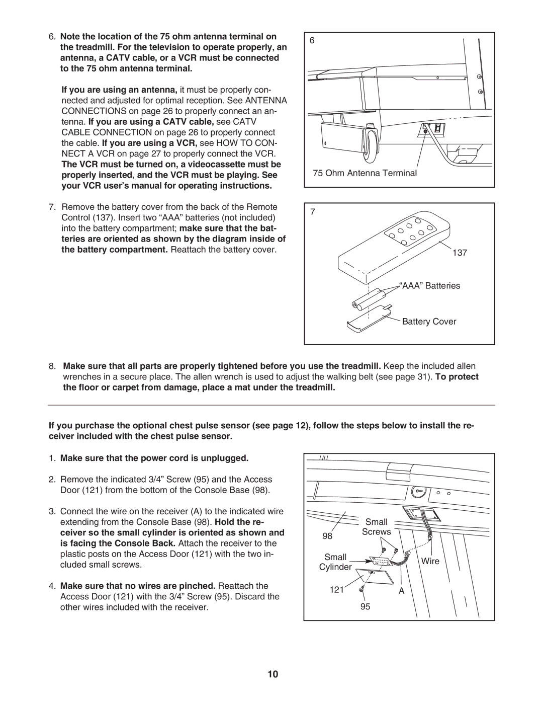
6.Note the location of the 75 ohm antenna terminal on the treadmill. For the television to operate properly, an antenna, a CATV cable, or a VCR must be connected to the 75 ohm antenna terminal.
If you are using an antenna, it must be properly con- nected and adjusted for optimal reception. See ANTENNA CONNECTIONS on page 26 to properly connect an an- tenna. If you are using a CATV cable, see CATV CABLE CONNECTION on page 26 to properly connect the cable. If you are using a VCR, see HOW TO CON- NECT A VCR on page 27 to properly connect the VCR.
The VCR must be turned on, a videocassette must be properly inserted, and the VCR must be playing. See your VCR user’s manual for operating instructions.
7.Remove the battery cover from the back of the Remote Control (137). Insert two “AAA” batteries (not included) into the battery compartment; make sure that the bat- teries are oriented as shown by the diagram inside of the battery compartment. Reattach the battery cover.
6 |
75 Ohm Antenna Terminal |
7 |
137 |
“AAA” Batteries
![]() Battery Cover
Battery Cover
8.Make sure that all parts are properly tightened before you use the treadmill. Keep the included allen wrenches in a secure place. The allen wrench is used to adjust the walking belt (see page 31). To protect the floor or carpet from damage, place a mat under the treadmill.
If you purchase the optional chest pulse sensor (see page 12), follow the steps below to install the re- | |||
ceiver included with the chest pulse sensor. |
|
| |
1. | Make sure that the power cord is unplugged. |
|
|
2. | Remove the indicated 3/4” Screw (95) and the Access |
|
|
| Door (121) from the bottom of the Console Base (98). |
|
|
3. | Connect the wire on the receiver (A) to the indicated wire |
|
|
| extending from the Console Base (98). Hold the re- |
| Small |
| ceiver so the small cylinder is oriented as shown and | 98 | Screws |
| is facing the Console Back. Attach the receiver to the |
| |
|
|
| |
| plastic posts on the Access Door (121) with the two in- | Small | Wire |
| cluded small screws. | ||
| Cylinder | ||
|
| ||
4. | Make sure that no wires are pinched. Reattach the | 121 | A |
| Access Door (121) with the 3/4” Screw (95). Discard the | ||
|
| 95 | |
| other wires included with the receiver. |
| |
10
