UNI-3 specifications
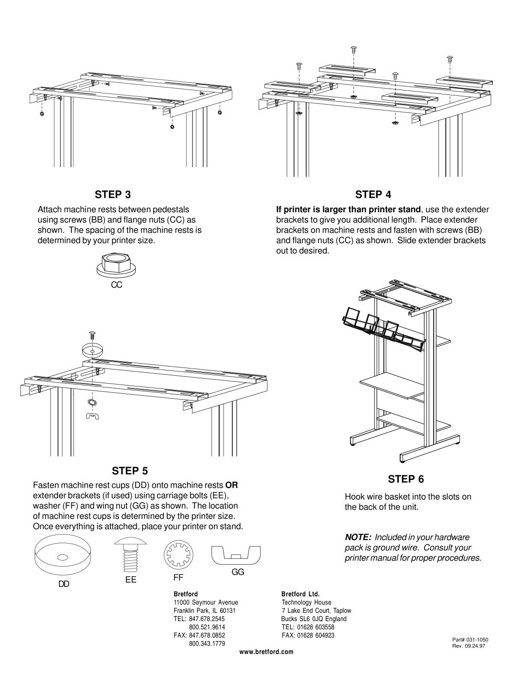
The Bretford UNI-3 is a versatile and innovative solution designed to meet the demands of modern workspaces and educational environments. Engineered with functionality and user experience in mind, the UNI-3 stands out as an essential tool for mobility, collaboration, and technology integration.One of the main features of the Bretford UNI-3 is its modular design. This versatility allows for seamless configuration adjustments, making it suitable for a variety of settings, from classrooms to corporate offices. Users can easily reconfigure the setup to accommodate different group sizes and meeting styles, promoting a dynamic workspace environment.
The UNI-3 is equipped with advanced technology integration options. It includes built-in power outlets and USB charging ports, enabling users to power their devices conveniently. This feature is crucial in today's digital age, where staying connected is essential. The tabletop also incorporates spaces for cable management, ensuring a tidy and organized appearance, which reduces clutter and distractions in collaborative settings.
Another highlight of the Bretford UNI-3 is its mobility. The unit comes with lockable wheels, allowing users to effortlessly move it between locations. This mobility fosters a flexible work approach, adapting to the evolving needs of a project or class. Whether it’s a quick group discussion or a larger collaborative session, the Bretford UNI-3 can quickly adjust to these changing dynamics.
Durability is another critical characteristic of the UNI-3. Made from high-quality materials, it is designed to withstand the rigors of daily use, making it an excellent investment for institutions and companies alike. The finish is resistant to scratches and stains, ensuring that the surface remains pristine over time.
In terms of aesthetics, the Bretford UNI-3 is available in multiple finishes and colors, allowing organizations to select options that best fit their brand or interior design. This attention to style ensures that while the unit is highly functional, it also enhances the overall aesthetic of the space.
In summary, the Bretford UNI-3 is a well-rounded solution that combines flexibility, technology integration, mobility, durability, and style. Whether in educational settings or corporate environments, it promotes effective collaboration and productivity, making it a valuable asset for any modern workspace.

