INSTALLATION
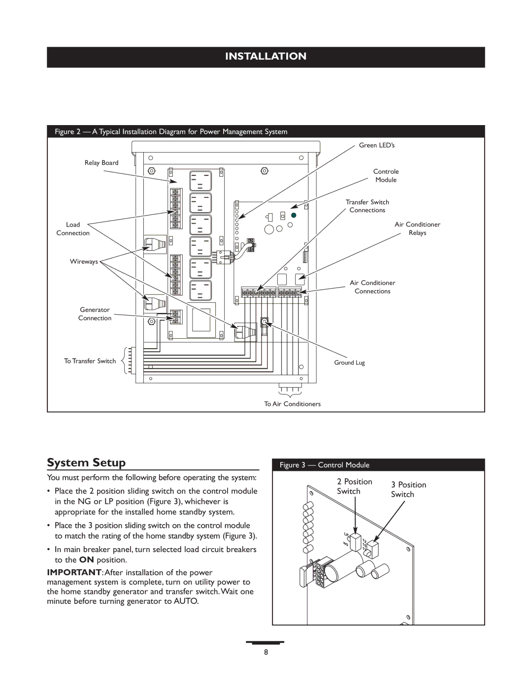
Figure 2 — A Typical Installation Diagram for Power Management System
Relay Board
Load
Connection
Wireways ![]()
Generator
Connection ![]()
To Transfer Switch
Green LED’s
Controle
Module
Transfer Switch
Connections
Air Conditioner
Relays
Air Conditioner
Connections
Ground Lug
To Air Conditioners
System Setup
You must perform the following before operating the system:
•Place the 2 position sliding switch on the control module in the NG or LP position (Figure 3), whichever is appropriate for the installed home standby system.
•Place the 3 position sliding switch on the control module to match the rating of the home standby system (Figure 3).
•In main breaker panel, turn selected load circuit breakers to the ON position.
IMPORTANT:After installation of the power management system is complete, turn on utility power to the home standby generator and transfer switch.Wait one minute before turning generator to AUTO.
Figure 3 — Control Module
2 Position | 3 Position | |
Switch | ||
Switch | ||
|
8