Illustrated Parts Manual
Foreword
Table of Contents
Main Component
Hydrostatic Ground
Steering Control Assemblies
Spread Tail Wheel Axle KIT
General Information
Glossary
Identifying Number Locations
Fill In By Purchaser
Servicing of Engine and Drivetrain Components
Specifications
Engine
Electrical System
Transmission
Tire Pressure
Blade Drive
Tire Size
Mower Deck
Drive Belts
Seat
FRAME/BODY Construction
Component Identification
Front View and Right Side View
Rear View and Left Side View
Top View Body Raised
Do not mow with bystanders in the area
Safety Instructions
Before Operating
Operating
Maintenance
Case of a clogged or plugged mower deck
Safety Instructions
SAFETY, CONTROL, and Instruction Decals
SAFETY, CONTROL, and Instruction Decals
Assembly Instructions
Setup Instructions
Battery Service
Deck Caster Wheel Installation
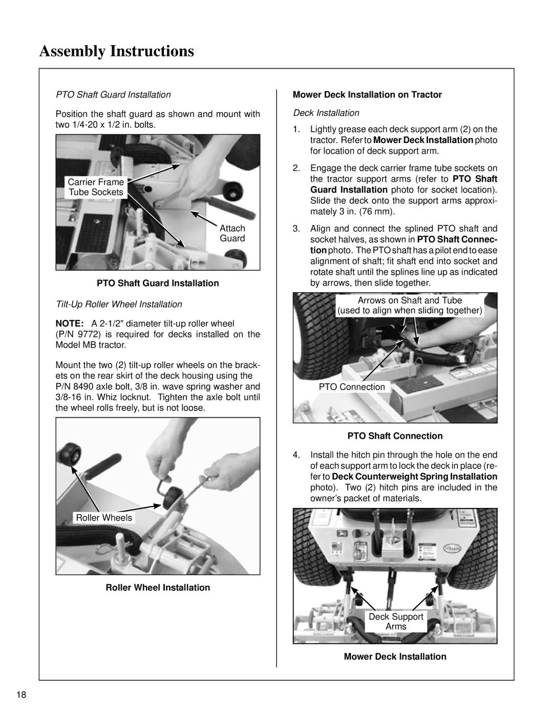
PTO Shaft Guard Installation
Deck Installation
Mower Deck Installation
PTO Shaft Connection
Deck Counterweight Spring Installation
Deck Leveling
Body Rod in Engaged Position
Body Rod in Stowed Position
Check Engine Crankcase OIL Level
Adjust Mower Cutting HEIGHT, if RE- Quired
Operating Controls
Operating Instructions
Control IDENTIFICATION, LOCATION, and Function
PTO Switch
Engine Choke
Engine Throttle
Choke and Throttle Location Forward Speed Control FSC
Hydro Lockout Rod Location Hourmeter
Left Wheel Right Wheel Steering Lever
Operating Controls Top View from Drivers Point of View
Disengaged
Adjusting Ground Speed and Steering
Starting the Engine
Correct Operator Hand Position on the Controls
Engaging the Mower
Blade Clutch Engaged Blade Clutch Disengaged
Cutting Height Adjustment
Stopping the Machine
Transaxle Lockouts
Hydro Lockout Rod Freewheel Position
Hydro Lockout Rod Normal Operating Position
Recommendations for Mowing
Side Discharge Shield in Lowest Position
Maximum Recommended Side Slope
Maintenance Instructions
Service Item 100 250 Daily Hours Yearly
Important Tips for Care of the Briggs & Stratton Engine
Lubrication
Engine Oil
Each USE
Dipstick Operating Range
Dipstick and Oil Fill View from above left side of tractor
Grease Fitting and Oil Point Lubrication
Lubrication
Maintenance Instructions
Mower Deck Gearbox Lubrication
Transaxle Lubrication
Cleaning
Keep Engine Screen Clean
Transaxle Oil Filter Location
Transaxle Drain Plugs View from underside of tractor
Cleaning
Clean Cooling Fins and Fan Air Cleaner System
Deck Secured in Tilt-Up Position
CHECKING/SERVICING
Battery
Cleaning the Terminals
Batteries Produce Explosive Gases
Tire Pressure
Drive Belts
Mower Blade Profile For Sharpening
Blade Balanced on Magnetic Wall-Mounted Balancer
REPLACING/REPAIRING
Spark Plugs
Breaker Points
Belt Locations
Engine/PTO Belt
Remove Belt Guard
Engine/PTO Belt Disengaged
Engine/PTO Belt Engaged
Ground Drive Belt Assembly Disengaged
Ground Drive Belt Assembly Engaged
Fuel Filter
Fuel Filter Location
Cutting Blade Shear Bolts
PTO Shear Pin
Mower Blades
Adjustments
Steering Lever Position Adjustment Step
Stop Bolt Location Stop Bolt Adjustment
Steering Handles Adjustment Step
Steering Lever Adjustment
Neutral Position Adjustment Step
FSC Position Steering Adjustment
Actuator Rod Length Adjustment
Full Forward Speed Adjustment Step
Straight Tracking Adjustment Step
Neutral Window
Neutral Travel End
Neutral Travel End Adjust
Neutral Switch Adjustment Step
FSC Switch Location
Forward Speed Control Friction Adjustment Step
ADJUSTMENTS/ Electrical System
Tilt-Up Deck Adjustable Stop
75$&725&$/6
0DLQWHQDQFHHFDOV
Refer to Decks Parts Manual 13 for Deck Decals
+$66,6$660%
7LOW8S/DWFK$VVHPEO\
Dvwhqhuv
KDVVLV$VVHPEO\
F009
$,1&203211732575$160,66,21
372ULYH$VVHPEO\ Dvwhqhuv
F051
KRNHDQG7KURWWOH$VVHPEOLHV
5283
XHO7DQN$VVHPEO\
F392
3DUNLQJ%UDNH$VVHPEO\
+5267$7,&*52815,9$660%/,6
URXQGULYH$VVHPEOLHV
F066
7UDQVPLVVLRQ6SULQJ$VVHPEOLHV
675,1*&21752/$660%/,6
6WHHULQJ/HYHU6&$VVHPEOLHV Dvwhqhuv
F183
75,&$/$660%
OHFWULFDO$VVHPEO\ Dvwhqhuv
Detail a
635$7$,/+/$/.,7
6SUHDG$OH.LW Dvwhqhuv
F016
6&+0$7
Limited Warranty For Walker Model MB Rider Mower
Sound Model MB
Sound Test