Smoke & Carbon Monoxide Alarm
AC Powered Smoke & Carbon Monoxide Alarm with Battery Back-up, Silence Feature and Latching Alarm
Model SC9120B
Input: 120V AC ~ , 60 Hz, 0.09A
•Connect this unit ONLY to other compatible units. See “How To Install This Smoke/CO Alarm” for details. Do not connect it to any other type of alarm or auxiliary device. Connecting anything else to this unit may damage it or prevent it from operating properly.
•The battery compartment resists closing unless a battery is installed. This warns you the unit will not operate under DC power without a battery.
•Do not stand too close to the unit when the alarm is sounding. It is loud to wake you in an emergency. Exposure to the horn at close range may harm your hearing.
•Do not paint over the unit. Paint may clog the openings to the sensing chambers and prevent the unit from operating properly.
INSTALLATION
WHERE TO INSTALL THIS ALARM
Minimum coverage for Smoke Alarms, as recommended by the National Fire Protection Association (NFPA), is one Smoke Alarm on every floor, in every sleeping area, and in every bedroom (See “Regulatory Information For Smoke Alarms” for details on the NFPA rec- ommendations).
For CO Alarms, the National Fire Protection Association (NFPA) recom- mends that a CO Alarm should be centrally located outside of each sep-
BEFORE YOU BEGIN INSTALLATION
This unit is designed to be mounted on any standard wiring junction box up to a 4-inch (10 cm) size, on either the ceiling or wall. Read “Where to Install This Alarm” and “Where This Alarm Should Not Be Installed ” before you begin installation. If a junction box is not already in place, install one using standard #12 or #14 gauge copper wire.
•Make sure the alarm is not receiving excessively noisy power. Examples of noisy power could be major appliances on the same circuit, power from a generator or solar power, light dim- mer on the same circuit or mounted near fluorescent lighting. Excessively noisy power may cause damage to your Alarm.
Find the pair of self-adhesive labels included with this Smoke/CO Alarm.
•On each label write in the phone number of your emergency responder (like 911) and a qualified appliance technician.
•Place one label near the Smoke/CO Alarm, and the other label in the “fresh air” location you plan to go if the alarm sounds.
NOTE: A qualified appliance technician is defined as “a person, firm, corporation, or company that either in person or through a representa- tive, is engaged in and responsible for the installation, testing, servicing, or replacement of heating, ventilation, air conditioning (HVAC) equipment, combustion appliances and equipment, and/or gas fireplaces or other decorative combustion equipment.”
ELECTRICAL SHOCK HAZARD. Do not restore power until all Alarms are completely installed. Restoring power before installation is complete may result in serious electrical shock, injury or death.
6. Make sure the Smoke/CO Alarm is receiving AC power. Under normal |
operation, the green indicator light will shine continuously. If the green |
power indicator light does not light, TURN OFF POWER TO THE |
JUNCTION BOX and recheck all connections. If all connections are |
correct and the green power indicator still does not light when you |
restore the power, the unit should be replaced immediately. |
7. ACTIVATING THE BATTERY BACK-UP |
Activate the battery back-up by removing the “Pull to Activate |
Battery Back-Up” tab. You do not need to open the battery |
compartment and reposition the battery during installation. DO NOT |
remove the battery activation tab until AC power is turned on to |
conserve battery power. |
8. Single Station Alarms: Test each Alarm. Press and hold the |
Test/Silence button until you hear the acknowledge “chirp” or the |
unit alarms. |
Interconnected Alarms: Press and hold the Test/Silence button |
until the unit alarms. All interconnected Alarms should sound. The |
other Alarms sounding only tests the interconnect signal between |
Alarms. It does not test each Alarm’s operation. You must test each |
THE COVER OF YOUR SMOKE/CO ALARM
1. Test/Silence Button: Press and hold to activate test, or to silence the alarm.
2. POWER Light (GREEN)/
SMOKE ALARM Light (RED)
3. CO ALARM Light (RED)
4. Battery Drawer
5. (Behind the Cover) Alarm Horn: 85dB audible alarm for test, alarm, and unit malfunction warning.
UNDERSTANDING THE LIGHT
AND HORN PATTERNS
Condition | LED (Red or Green | Horn |
| Lights) | |
| | |
POWER UP | Green LED | Horn remains silent |
| flashes ON | |
| once, then | |
Actuation of your CO Alarm indicates the presence of carbon monoxide (CO) which can kill you. In other words, when your CO Alarm sounds, you must not ignore it!
IF THE CO ALARM SOUNDS:
1. | Operate the Test/Silence button. |
2. | Call your emergency services, fire department or 911. Write down |
| the number of your local emergency service here: |
| _____________________________________________________________ |
3. | Immediately move to fresh air—outdoors or by an open door or |
| window. Do a head count to check that all persons are accounted |
| for. Do not re-enter the premises, or move away from the open door |
| or window until the emergency services responder has arrived, the |
| premises have been aired out, and your Smoke/CO Alarm remains in |
| its normal condition. |
4. | After following steps 1-3, if your Smoke/CO Alarm reactivates within |
| a 24-hour period, repeat steps 1-3 and call a qualified appliance |
| technician to investigate for sources of CO from fuel-burning equip- |
| ment and appliances, and inspect for proper operation of this equip- |
| ment. If problems are identified during this inspection have the |
| equipment serviced immediately. Note any combustion equipment |
| not inspected by the technician, and consult the manufacturers’ |
IMPORTANT! PLEASE READ CAREFULLY AND SAVE
This user’s manual contains important information about your Alarm’s operation. If you are installing the Alarm for use by others, you must leave this manual — or a copy of it — with the end user.
| Printed in Mexico | Model SC9120B |
| M08-0094-000 K1 09/04 |
| |
INTRODUCTION
Thank you for choosing BRK Brands, Inc. for your Smoke and Carbon Monoxide Alarm needs. You have purchased a state-of-the-art Smoke & CO Alarm designed to provide you with early warning of a fire or Carbon Monoxide. Key features include:
Smoke & Carbon Monoxide Combination Alarm. One alarm protects against two deadly household threats.
Intelligent Sensing Technology designed to help reduce unwanted or nuisance alarms.
Smart Interconnect can be interconnected to BRK Smoke Alarms. One interconnect wire carries both smoke and CO alarm signals.
arate sleeping area in the immediate vicinity of the bedrooms. For added protection, install additional CO Alarms in each separate bedroom, and on every level of your home.
In general, install combination Smoke and Carbon Monoxide Alarms:
•On every level of your home, including finished attics and base- ments.
•Inside every bedroom, especially if people sleep with the door partly or completely closed.
•In the hall near every sleeping area. If your home has multiple sleeping areas, install a unit in each. If a hall is more than 40 feet (12 meters) long, install a unit at each end.
•At the top of first-to-second floor stairs.
•At the bottom of the basement stairs.
•For additional coverage, install Alarms in all rooms, halls, and stor- age areas, where temperatures normally remain between 40˚ F and 100˚ F (4˚ C and 38˚ C).
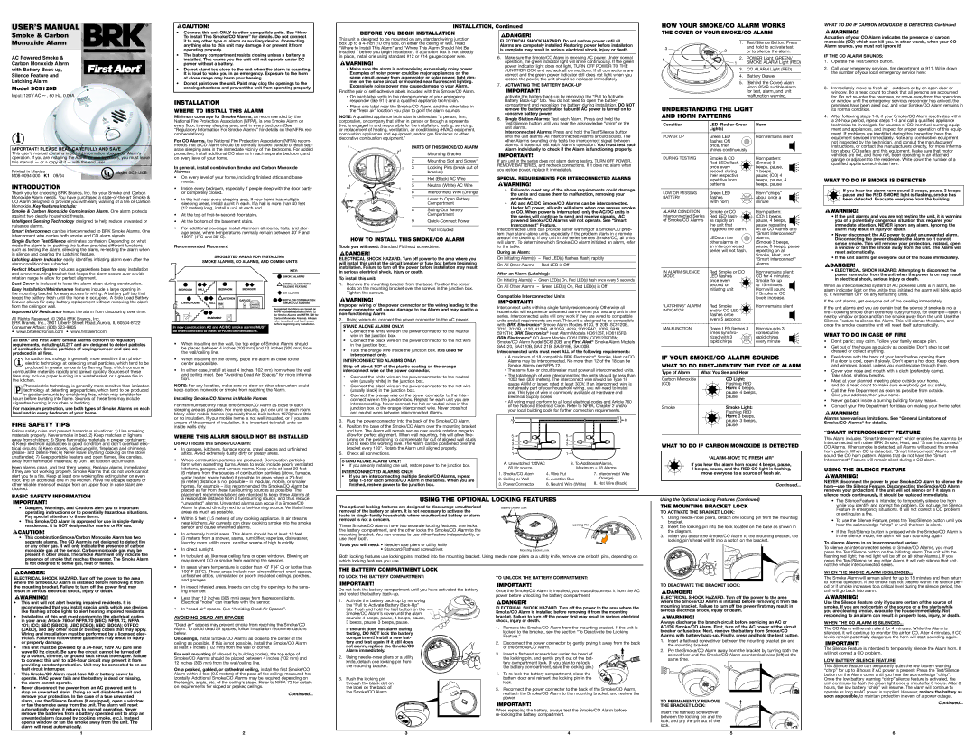
PARTS OF THIS SMOKE/CO ALARM
1Mounting Bracket
2Mounting Slot and Screw*
3Locking Pins (break out of bracket)
4Hot (Black) AC Wire
5Neutral (White) AC Wire
6Interconnect Wire (Orange)
7Lever to Open Battery Compartment
8Swing-Out Battery Compartment
9Quick-Connect Power *Not Included
Alarm individually to check if the Alarm is functioning properly. |
If any unit in the series does not alarm during testing, TURN OFF POWER, REMOVE BATTERIES, and recheck connections. If it does not alarm when you restore power, replace it immediately.
SPECIAL REQUIREMENTS FOR INTERCONNECTED ALARMS
•Failure to meet any of the above requirements could damage the units and cause them to malfunction, removing your protection.
•AC and AC/DC Smoke/CO Alarms can be interconnected. Under AC power, all units will alarm when one senses smoke or CO. When power is interrupted, only the AC/DC units in the series will continue to send and receive signals. AC powered Smoke/CO Alarms will not operate. See “Smart Interconnect” Feature.
Interconnected units can provide earlier warning of a Smoke/CO prob- lem than stand-alone units, especially if the problem starts in a remote
| shines continuously | |
DURING TESTING | Smoke & CO | Horn pattern: |
| Red LEDs flash | (Smoke) 3 |
| once every | beeps, pause, |
| second during | 3 beeps, |
| their respective | pause; (CO) 4 |
| repetitive horn | beeps, pause, 4 |
| patterns | beeps, pause |
LOW OR MISSING | Green LED | Horn “chirps” |
BATTERY | flashes | about once a |
| (with horn) | minute |
ALARM CONDITION | Smoke or CO | Horn pattern: |
Interconnected Series | Red LED flash- | (CO) 4 beeps, |
of Smoke/CO Alarms | es rapidly on | pause, 4 beeps, |
| the unit that | pause repeating |
| triggered the alarm. | on all CO Alarms and |
| | “Smart Interconnect” |
| LEDs on the | Alarms; |
instructions, or contact the manufacturers directly, for more informa- |
tion about CO safety and this equipment. Make sure that motor |
vehicles are not, and have not, been operating in an attached |
garage or adjacent to the residence. Write down the number of a |
qualified appliance technician here: |
_____________________________________________________________ |
WHAT TO DO IF SMOKE IS DETECTED
 If you hear the alarm horn sound 3 beeps, pause, 3 beeps, pause and the RED SMOKE light is flashing, smoke has been detected. Evacuate everyone from the building.
• If the unit alarms and you are not testing the unit, it is warning |
you of a potentially dangerous situation that requires your |
immediate attention. NEVER ignore any alarm. Ignoring the |
alarm may result in injury or death. |
• Never disconnect the AC power to quiet an unwanted alarm. |
Single Button Test/Silence eliminates confusion. Depending on what mode the alarm is in, pushing the button provides different functions such as testing the alarm, silencing the alarm, re-testing the alarm when in silence and clearing the Latching feature.
Latching Alarm Indicator easily identifies initiating alarm even after the alarm condition has subsided.
Perfect Mount System includes a gasketless base for easy installation and a new mounting bracket that keeps the alarm secure over a wide rotation range to allow for perfect alignment.
Dust Cover is included to keep the alarm clean during construction.
Easy Installation/Maintenance features include a large opening in the mounting bracket for easy access to wiring. A battery pull tab that keeps the battery fresh until the home is occupied. A Side Load Battery Drawer allows for easy battery replacement without removing the alarm from the ceiling or wall.
Improved UV Resistance keeps the alarm from discoloring over time.
All Rights Reserved. © 2004 BRK Brands, Inc.
BRK Brands, Inc., 3901 Liberty Street Road, Aurora, IL 60504-8122 Consumer Affairs: (800) 323-9005
• www.brkelectronics.com • www.firstalert.com
All BRK® and First Alert® Smoke Alarms conform to regulatory requirements, including UL217 and are designed to detect particles of combustion. Smoke particles of varying number and size are produced in all fires.
Ionization technology is generally more sensitive than photo- electric technology at detecting small particles, which tend to be produced in greater amounts by flaming fires, which consume
combustible materials rapidly and spread quickly. Sources of these fires may include paper burning in a wastebasket, or a grease fire in the kitchen.
Photoelectric technology is generally more sensitive than ionization technology at detecting large particles, which tend to be produced in greater amounts by smoldering fires, which may smolder for
hours before bursting into flame. Sources of these fires may include cigarettes burning in couches or bedding.
For maximum protection, use both types of Smoke Alarms on each level and in every bedroom of your home.
FIRE SAFETY TIPS
Follow safety rules and prevent hazardous situations: 1) Use smoking materials properly. Never smoke in bed. 2) Keep matches or lighters away from children; 3) Store flammable materials in proper containers;
4)Keep electrical appliances in good condition and don’t overload elec- trical circuits; 5) Keep stoves, barbecue grills, fireplaces and chimneys grease- and debris-free; 6) Never leave anything cooking on the stove unattended; 7) Keep portable heaters and open flames, like candles, away from flammable materials; 8) Don’t let rubbish accumulate.
Keep alarms clean, and test them weekly. Replace alarms immediately if they are not working properly. Smoke Alarms that do not work cannot alert you to a fire. Keep at least one working fire extinguisher on every floor, and an additional one in the kitchen. Have fire escape ladders or other reliable means of escape from an upper floor in case stairs are blocked.
Recommended Placement
SUGGESTED AREAS FOR INSTALLING
SMOKE ALARMS, CO ALARMS, AND COMBO UNITS
KEY:
SMOKE ALARMS
SMOKE ALARM WITH
SILENCE FEATURE
 CO ALARMS

 BOTH, OR COMBINATION
SMOKE/CO ALARMS
Suggested locations are based on NFPA recommendations (NFPA 72 for Smoke Alarms and NFPA 720 for Carbon Monoxide Alarms). Always refer to national and local codes before beginning any installation.
In new construction AC and AC/DC smoke alarms MUST be interconnected to meet NFPA recommendations.
•When installing on the wall, the top edge of Smoke Alarms should be placed between 4 inches (102 mm) and 12 inches (305 mm) from the wall/ceiling line.
•When installing on the ceiling, place the alarm as close to the center as possible.
•In either case, install at least 4 inches (102 mm) from where the wall and ceiling meet. See “Avoiding Dead Air Spaces” for more informa- tion.
NOTE: For any location, make sure no door or other obstruction could keep carbon monoxide or smoke from reaching the Alarm.
Installing Smoke/CO Alarms in Mobile Homes
For minimum security install one Smoke/CO Alarm as close to each sleeping area as possible. For more security, put one unit in each room. Many older mobile homes (especially those built before 1978) have little or no insulation. If your mobile home is not well insulated, or if you are unsure of the amount of insulation, it is important to install units on inside walls only.
WHERE THIS ALARM SHOULD NOT BE INSTALLED
Do NOT locate this Smoke/CO Alarm:
• In garages, kitchens, furnace rooms, crawl spaces and unfinished |
attics. Avoid extremely dusty, dirty or greasy areas. |
• Where combustion particles are produced. Combustion particles |
form when something burns. Areas to avoid include poorly ventilated |
kitchens, garages, and furnace rooms. Keep units at least 20 feet |
(6 meters) from the sources of combustion particles (stove, furnace, |
water heater, space heater) if possible. In areas where a 20-foot |
(6 meter) distance is not possible – in modular, mobile, or smaller |
homes, for example – it is recommended the Smoke/CO Alarm be |
placed as far from these fuel-burning sources as possible. The |
HOW TO INSTALL THIS SMOKE/CO ALARM
Tools you will need: Standard Flathead screwdriver.
ELECTRICAL SHOCK HAZARD. Turn off power to the area where you will install this unit at the circuit breaker or fuse box before beginning installation. Failure to turn off the power before installation may result in serious electrical shock, injury or death.
To install this unit:
1.Remove the mounting bracket from the base. Position the screw slots on the mounting bracket over the screws in the junction box. Tighten the screws.
Improper wiring of the power connector or the wiring leading to the power connector will cause damage to the Alarm and may lead to a non-functioning Alarm.
2. Using wire nuts, connect the power connector to the AC power.
STAND ALONE ALARM ONLY:
•Connect the white wire on the power connector to the neutral wire in the junction box.
•Connect the black wire on the power connector to the hot wire in the junction box.
•Tuck the orange wire inside the junction box. It is used for interconnect only.
INTERCONNECTED ALARMS ONLY:
Strip off about 1/2” of the plastic coating on the orange interconnect wire on the power connector.
•Connect the white wire on the power connector to the neutral wire (usually white) in the junction box.
•Connect the black wire on the power connector to the hot wire (usually black) in the junction box.
•Connect the orange wire on the power connector to the inter- connect wire in the junction box. Repeat for each unit you are interconnecting. Never connect the hot or neutral wires in the junction box to the orange interconnect wire. Never cross hot and neutral wires between interconnected Alarms.
3.Plug the power connector into the back of the Smoke/CO Alarm.
4.Position the base of the Smoke/CO Alarm over the mounting bracket and turn. The Alarm will remain secure over a wide rotation range to allow for perfect alignment. When wall mounting, this will allow fine- tuning on the positioning to compensate for out of aligned wall studs and to keep the wording level. The Alarm can be positioned over the bracket every 120°. Rotate the Alarm until aligned properly.
5.Check all connections.
STAND ALONE ALARM ONLY:
•If you are only installing one unit, restore power to the junction box.
INTERCONNECTED ALARMS ONLY:
•If you are interconnecting multiple Smoke/CO Alarms, repeat Step 1-5 for each Smoke/CO Alarm in the series. When you are finished, restore power to the junction box.
area of the dwelling. If any unit in the series senses Smoke/CO, all units will alarm. To determine which Smoke/CO Alarm initiated an alarm, refer to the table.
During an Alarm:
On Initiating Alarm(s) – Red LED(s) flashes (flash) rapidly
On All Other Alarms – Red LED is Off
After an Alarm (Latching):
On Initiating Alarm(s) – Green LED(s) On, Red LED(s) flash once every 5 seconds
On All Other Alarms – Green LED(s) On, Red LED(s) is Off
Compatible Interconnected Units
Interconnect units within a single family residence only. Otherwise all households will experience unwanted alarms when you test any unit in the series. Interconnected units will only work if they are wired to compatible units and all requirements are met. This unit is designed to be compatible with: BRK Electronics® Smoke Alarm Models 9120, 9120B, SC9120B, 7010, 7010B, 4120, 4120B, 4120SB, 4919, 2002RAC, 100S, 5919, 5919TH; BRK Electronics® Heat Alarm Models HD6135F, HD6135FB; BRK Electronics® CO Alarm Models CO5120BN, CO5120PDBN; Smoke/CO Alarm Model SC6120B; and First Alert® Smoke Alarm Models SA4120, SA4120B, SA4121B, SA4919B, SA100B.
Interconnected units must meet ALL of the following requirements:
•A maximum of 18 compatible BRK Electronics® Smoke, Heat or CO Alarms may be interconnected. No more than 12 of the 18 can be Smoke Alarms per NFPA 72.
•The same fuse or circuit breaker must power all interconnected units.
•The total length of wire interconnecting the units should be less than 1000 feet (300 meters). The interconnect wire should be Type 18 gauge AWM or larger, rated at least 300V. If an interconnect wire is not already part of your household wiring, you will need to install one. This type of wire is commonly available at Hardware and Electrical Supply stores.
•All wiring must conform to all local electrical codes and Article 760 of the National Electrical Code. Refer to NFPA, Chapter 2 and/or your local building code for further connection requirements.
| A. Unswitched 120VAC | | B. To Additional Alarms, | |
| 60 Hz source | | Maximum = 18 Alarms | |
| | | | | |
| | | | |
1. | Smoke/CO Alarm | 4. | Wire Nut | 7. Interconnect Wire |
2. | Ceiling or Wall | 5. | Junction Box | (Orange) |
3. | Power Connector | 6. Neutral Wire (White) | 8. Hot Wire (Black) |
| | | | | |
| other alarms in | (Smoke) 3 beeps, |
| an interconnected | pause, 3 beeps, pause |
| series will not flash. | repeating on all |
| | Smoke, Heat, and |
| | “Smart Interconnect” |
| | Alarms |
IN ALARM SILENCE | Red Smoke or CO | Horn remains silent: |
MODE | LED flashes | CO for 4 minutes; |
| once every | Smoke for up |
| second on | to 15 minutes. |
| initiating unit | Horn will sound |
| | if Smoke or CO |
| | levels increase. |
“LATCHING” ALARM | Red Smoke | Horn remains silent |
INDICATOR | and/or CO LED | |
| flashes once | |
| every 5 seconds | |
MALFUNCTION | Green LED flashes 3 | Horn sounds 3 |
| times synchro- | consecutive |
| nized with 3 | rapid chirps |
| rapid chirps | every minute |
IF YOUR SMOKE/CO ALARM SOUNDS
WHAT TO DO FIRST–IDENTIFY THE TYPE OF ALARM
Type of Alarm | What You See and Hear |
Carbon Monoxide | CO Light: |
(CO) | Flashing RED |
| Horn: 4 beeps, |
| pause, 4 beeps, |
| pause |
Smoke | Smoke Light: |
| Flashing RED |
| Horn: 3 beeps, |
| pause, 3 beeps, |
| pause |
WHAT TO DO IF CARBON MONOXIDE IS DETECTED
“ALARM-MOVE TO FRESH AIR”
If you hear the alarm horn sound 4 beeps, pause, 4 beeps, pause, and the RED CO light is flashing, move everyone to a source of fresh air.
Continued...
Disconnecting the power disables the Alarm so it cannot |
sense smoke. This will remove your protection. Instead, open |
a window or fan the smoke away from the unit. The Alarm will |
reset automatically. |
• If the unit alarms get everyone out of the house immediately. |
• ELECTRICAL SHOCK HAZARD: Attempting to disconnect the |
power connector from the unit when the power is on may result |
in electrical shock, serious injury or death. |
When an interconnected system of AC powered units is in alarm, the alarm indicator light on the unit(s) that initiated the alarm will blink rapid- ly. It will remain OFF on any remaining units.
If the unit alarms, get everyone out of the dwelling immediately.
If the unit alarms and you are certain that the source of smoke is not a fire—cooking smoke or an extremely dusty furnace, for example—open a nearby window or door and fan the smoke away from the unit. Use the Silence Feature to silence the Alarm. This will silence the alarm, and once the smoke clears the unit will reset itself automatically.
WHAT TO DO IN CASE OF FIRE
•Don’t panic; stay calm. Follow your family escape plan.
•Get out of the house as quickly as possible. Don’t stop to get dressed or collect anything.
•Feel doors with the back of your hand before opening them.
If a door is cool, open it slowly. Don’t open a hot door. Keep doors and windows closed, unless you must escape through them.
•Cover your nose and mouth with a cloth (preferably damp). Take short, shallow breaths.
•Meet at your planned meeting place outside your home, and do a head count to make sure everybody got out safely.
•Call the Fire Department as soon as possible from outside. Give your address, then your name.
•Never go back inside a burning building for any reason.
•Contact your Fire Department for ideas on making your home safer.
Alarms have various limitations. See "General Limitations of Smoke/CO Alarms" for details.
“SMART INTERCONNECT” FEATURE
This Alarm includes "Smart Interconnect" which enables the Alarm to be interconnected with other BRK Smoke, Heat, and "Smart Interconnect" CO Alarms. When smoke is detected, all Alarms will sound the smoke horn pattern. When CO is detected, "Smart Interconnect" Alarms will sound the CO horn pattern. Alarms that do not have the "Smart Interconnect" Feature will remain silent during a CO alarm.
USING THE SILENCE FEATURE
NEVER disconnect the power to your Smoke/CO Alarm to silence the horn—use the Silence Feature. Disconnecting the Smoke/CO Alarm removes your protection! If the unit will not silence or if it stays in
BASIC SAFETY INFORMATION
•Dangers, Warnings, and Cautions alert you to important operating instructions or to potentially hazardous situations. Pay special attention to these items.
•This Smoke/CO Alarm is approved for use in single-family residences. It is NOT designed for marine or RV use.
•This combination Smoke/Carbon Monoxide Alarm has two separate alarms. The CO Alarm is not designed to detect fire or any other gas. It will only indicate the presence of carbon monoxide gas at the sensor. Carbon monoxide gas may be present in other areas. The Smoke Alarm will only indicate the presence of smoke that reaches the sensor. The Smoke Alarm is not designed to sense gas, heat or flames.
placement recommendations are intended to keep these Alarms at |
a reasonable distance from a fuel-burning source, and thus reduce |
“unwanted” alarms. Unwanted alarms can occur if a Smoke/CO |
Alarm is placed directly next to a fuel-burning source. Ventilate these |
areas as much as possible. |
• Within 5 feet (1.5 meters) of any cooking appliance. In air streams |
near kitchens. Air currents can draw cooking smoke into the smoke |
sensor and cause unwanted alarms. |
• In extremely humid areas. This Alarm should be at least 10 feet |
(3 meters) from a shower, sauna, humidifier, vaporizer, dishwasher, |
laundry room, utility room, or other source of high humidity. |
• In direct sunlight. |
• In turbulent air, like near ceiling fans or open windows. Blowing air |
may prevent CO or smoke from reaching the sensors. |
• In areas where temperature is colder than 40˚ F (4˚ C) or hotter than |
USING THE OPTIONAL LOCKING FEATURES
The optional locking features are designed to discourage unauthorized | Battery Drawer Lock |
removal of the battery or alarm. It is not necessary to activate the | |
locks in single-family households where unauthorized battery or alarm | |
removal is not a concern. | |
These Smoke/CO Alarms have two separate locking features: one locks | Locking Pin |
the battery compartment, and the other locks the Smoke/CO Alarm to the | |
mounting bracket. You can choose to use either feature independently, or | |
use them both. | |
Tools you will need: • Needle-nose pliers or utility knife | |
• Standard/Flathead screwdriver. | Mounting Bracket Lock |
Both locking features use locking pins, molded into the mounting bracket. Using needle nose pliers or a utility knife, remove one or both pins, depending on which locking features you use.
Using the Optional Locking Features (Continued)
THE MOUNTING BRACKET LOCK
TO ACTIVATE THE BRACKET LOCK:
1.Using needle-nose pliers, detach one locking pin from the mounting bracket.
2.Insert the locking pin into the lock located on the base as shown in the diagram.
3.When you attach the Smoke/CO Alarm to the mounting bracket, the locking pin’s head will fit into a notch on the bracket.
silence mode continuously, it should be replaced immediately.
•The Silence Feature is intended to temporarily silence the horn while you identify and correct the problem. Do not use the Silence Feature in emergency situations. It will not correct a CO problem or extinguish a fire.
•To use the Silence Feature, press the Test/Silence button until you hear the acknowledge “chirp” or until the horn is silent.
•If the Test/Silence button is pressed while the Smoke/CO Alarm is in the silence mode, the alarm will start sounding again.
To silence Alarms in an interconnected series:
To silence an interconnected series of Smoke/CO Alarms, you must press the Test/Silence button on the initiating alarm (The unit with the flashing red light; the red light will be off on all other Alarms.). If you press the Test/Silence on any other Alarm, it will only silence that unit, not the whole interconnected series.
ELECTRICAL SHOCK HAZARD. Turn off the power to the area where the Smoke/CO Alarm is installed before removing it from the mounting bracket. Failure to turn off the power first may result in serious electrical shock, injury or death.
•This unit will not alert hearing impaired residents. It is recommended that you install special units which use devices like flashing strobe lights to alert hearing impaired residents.
•Installation of this unit must conform to the electrical codes in your area; Article 760 of NFPA 70 (NEC), NFPA 72, NFPA 101; ICC; SBC (SBCCI); UBC (ICBO); NBC (BOCA); OTFDC (CABO), and any other local or building codes that may apply. Wiring and installation must be performed by a licensed elec- trician. Failure to follow these guidelines may result in injury or property damage.
•This unit must be powered by a 24-hour, 120V AC pure sine wave 60 Hz circuit. Be sure the circuit cannot be turned off by a switch, dimmer, or ground fault circuit interrupter. Failure to connect this unit to a 24-hour circuit may prevent it from providing constant protection. Unit may be connected to an arc fault circuit interrupter.
•This Smoke/CO Alarm must have AC or battery power to operate. If AC power fails and the battery is dead or missing, the alarm cannot operate.
•Never disconnect the power from an AC powered unit to stop an unwanted alarm. Doing so will disable the unit and remove your protection. In the case of a true unwanted alarm, use the Silence Feature (if equipped), open a window or fan the smoke away from the unit. The alarm will reset automatically when it returns to normal operation. Never remove the batteries from a battery operated unit to stop an unwanted alarm (caused by cooking smoke, etc.). Instead open a window or fan the smoke away from the unit. The alarm will reset automatically.
100˚ F (38˚C). These areas include non-airconditioned crawl spaces, |
unfinished attics, uninsulated or poorly insulated ceilings, porches, |
and garages. |
• In insect infested areas. Insects can clog the openings to the sens- |
ing chamber. |
• Less than 12 inches (305 mm) away from fluorescent lights. |
Electrical “noise” can interfere with the sensor. |
• In “dead air” spaces. See “Avoiding Dead Air Spaces”. |
AVOIDING DEAD AIR SPACES
“Dead air” spaces may prevent smoke from reaching the Smoke/CO Alarm. To avoid dead air spaces, follow installation recommendations below.
On ceilings, install Smoke/CO Alarms as close to the center of the ceiling as possible. If this is not possible, install the Smoke/CO Alarm at least 4 inches (102 mm) from the wall or corner.
For wall mounting (if allowed by building codes), the top edge of Smoke/CO Alarms should be placed between 4 inches (102 mm) and 12 inches (305 mm) from the wall/ceiling line.
On a peaked, gabled, or cathedral ceiling, install the first Smoke/CO Alarm within 3 feet (0.9 meters) of the peak of the ceiling, measured hor- izontally. Additional Smoke/CO Alarms may be required depending on the length, angle, etc. of the ceiling's slope. Refer to NFPA 72 for details on requirements for sloped or peaked ceilings.
Continued...
THE BATTERY COMPARTMENT LOCK
TO LOCK THE BATTERY COMPARTMENT:
Do not lock the battery compartment until you have activated the battery and tested the battery back-up.
1. Activate the battery back-up by removing the “Pull to Activate Battery Back-Up” tab. Push and hold the test button on the Smoke/CO Alarm’s cover until the alarm sounds: 4 beeps, pause, 4 beeps, pause, 3 beeps, pause, 3 beeps, pause.
If the unit does not alarm during testing, DO NOT lock the battery compartment! Install a new bat- tery and test again. If it still does not alarm, replace the Smoke/CO Alarm immediately.
2. Using needle-nose pliers or a utility knife, detach one locking pin from the mounting bracket.
3.Push the locking pin through the black dot on
the label on the back of the Smoke/CO Alarm.
TO UNLOCK THE BATTERY COMPARTMENT:
Once the Smoke/CO Alarm is installed, you must disconnect it from the AC power before unlocking the battery compartment.
ELECTRICAL SHOCK HAZARD. Turn off the power to the area where the Smoke/CO Alarm is installed before removing it from the mounting bracket. Failure to turn off the power first may result in serious electrical shock, injury or death.
1.Remove the Smoke/CO Alarm from the mounting bracket. If the unit is locked to the bracket, see the section “To Deactivate the Locking Feature.”
2.Disconnect the power connector by gently prying it away from the back of the Smoke/CO Alarm.
3.Insert a flathead screwdriver under the head of
the locking pin, and gently pry it out of the bat- tery compartment lock. (If you plan to re-lock the battery compartment, save the locking pin.)
4. To re-lock the battery compartment, close the battery door and reinsert the locking pin in the lock.
5.Reconnect the power connector to the back of the Smoke/CO Alarm, reattach the Smoke/CO Alarm to the mounting bracket, and restore the power.
When replacing the battery, always test the Smoke/CO Alarm before re-locking the battery compartment.
TO DEACTIVATE THE BRACKET LOCK:
ELECTRICAL SHOCK HAZARD. Turn off the power to the area where the Smoke/CO Alarm is installed before removing it from the mounting bracket. Failure to turn off the power first may result in serious electrical shock, injury or death.
Always discharge the branch circuit before servicing an AC or AC/DC Smoke/CO Alarm. First, turn off the AC power at the circuit breaker or fuse box. Next, remove the battery from Smoke/CO Alarms with battery back-up. Finally, press and hold the test button.
1.Insert a flathead screwdriver between the mounting bracket pin and the mounting bracket.
2.Pry the Smoke/CO Alarm away from the bracket by turning both the screwdriver and the Smoke/CO Alarm counterclockwise (left) at the same time.
TO PERMANENTLY REMOVE
THE BRACKET LOCK:
Insert the flathead screwdriver between the locking pin and the lock, and pry the pin out of the lock.
WHEN THE SMOKE ALARM IS SILENCED...
The Smoke Alarm will remain silent for up to 15 minutes and then return to normal operation. If the smoke has not cleared within the silence peri- od or if smoke increases to a critical level during the silence period, the unit will go back into alarm.
Use the Silence Feature only if you are certain of the source of smoke. If you are not certain of the source or a fire starts while you are clearing smoke, evacuate the house immediately. Not responding to an alarm can result in property loss, injury, or death.
WHEN THE CO ALARM IS SILENCED...
The CO Alarm will remain silent for 4 minutes. While the Alarm is silenced, it will continue to monitor the air for CO. After 4 minutes, if CO levels remain potentially dangerous the horn will start sounding again.
The Silence Feature is intended to temporarily silence the Alarm horn. It will not correct a CO problem.
LOW BATTERY SILENCE FEATURE
This Silence Feature can temporarily quiet the low battery warning
“chirp” for up to 8 hours if AC power is present. Press the Test/Silence button on the Alarm cover until you hear the acknowledge “chirp”. Once the low battery warning “chirp” silence feature is activated, the unit continues to flash the green light once a minute for 8 hours. After 8 hours, the low battery “chirp” will resume. The Alarm will continue to operate as long as AC power is supplied. However, replace the battery as soon as possible, to maintain protection in event of a power outage.
Continued...