K. Install Horizontal Termination Cap
WARNING! Risk of Fire! The telescoping flue section of the termination cap MUST be used when connecting vent.
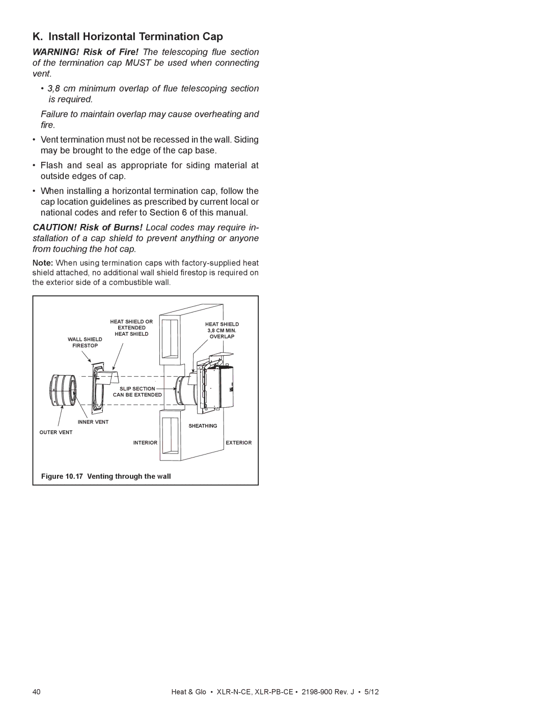
•3,8 cm minimum overlap of flue telescoping section is required.
Failure to maintain overlap may cause overheating and fire.
•Vent termination must not be recessed in the wall. Siding may be brought to the edge of the cap base.
•Flash and seal as appropriate for siding material at outside edges of cap.
•When installing a horizontal termination cap, follow the cap location guidelines as prescribed by current local or national codes and refer to Section 6 of this manual.
CAUTION! Risk of Burns! Local codes may require in- stallation of a cap shield to prevent anything or anyone from touching the hot cap.
Note: When using termination caps with
HEAT SHIELD OR | HEAT SHIELD | |
EXTENDED | ||
3,8 CM MIN. | ||
HEAT SHIELD | ||
OVERLAP | ||
WALL SHIELD | ||
| ||
FIRESTOP |
| |
SLIP SECTION |
| |
CAN BE EXTENDED |
| |
INNER VENT | SHEATHING | |
OUTER VENT | ||
| ||
INTERIOR | EXTERIOR | |
Figure 10.17 Venting through the wall |
|
40 | Heat & Glo • |