1. Top Vent - Horizontal Termination - (continued)
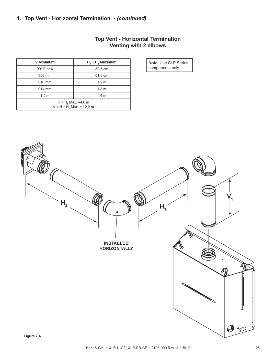
Top Vent - Horizontal Termination
Venting with 2 elbows
V Minimum |
| H1 + H2 Maximum |
90° Elbow |
| 30,5 cm |
|
|
|
305 mm |
| 61,0 cm |
|
|
|
610 mm |
| 1,2 m |
914 mm |
| 1,8 m |
|
|
|
1,2 m |
| 4,6 m |
|
|
|
| H + H1 Max. =4,6 m | |
V + H + H1 Max. = 12,2 m
Note: Use SLP Series components only.
H2
H1
INSTALLED
HORIZONTALLY
V1
Figure 7.4
Heat & Glo • | 25 |