NOTICE
•What to do if you smell gas
EC-87/09/058
Owner’s Manual
A. Congratulations
Homeowner Reference Information
GL Industries Ltd
Model
Table of Contents
Safety Alert Key
Installer Guide
3 Maintenance and Service
14 Appliance Setup
15 Troubleshooting
16 Component Access
= Contains updated information
B. Limited Lifetime Warranty
LIMITED LIFETIME WARRANTY
Hearth & Home Technologies Inc
WARRANTY COVERAGE
B. Limited Lifetime Warranty continued
WARRANTY CONDITIONS
WARRANTY EXCLUSIONS
This warranty is void if
C. Non-CombustibleMaterials Specification
D. Combustible Materials Specification
1 Listing and Code Approvals
A. Appliance Certification
A. Gas Fireplace Safety
2 Operating Instructions User Guide
B. Your Fireplace
WARNING! Choking Hazard! Keep glass rock media
F. Fixed Glass Assembly
C. Clear Space
D. Decorative Doors and Fronts
E. Decorative Media Options
5.Module Reset Switch
I. Control Module Operation
Nine Hour Safety Shutdown Feature
J. Lighting Instructions IPI
Final inspection by
FOR YOUR SAFETY READ BEFORE LIGHTING
Also Certified for Installation in a
K. Battery Tray/Battery Installation
M. Frequently Asked Questions
L. After Fireplace is Lit
Initial Break-inProcedure
3 Maintenance and Service
A. Maintenance Tasks-Homeowner
Glass Cleaning
Decorative Doors
B.Maintenance Tasks-QualifiedService Technician
Gasket Seal and Glass Assembly Inspection
Firebox
Control Compartment and Firebox Top
4 Getting Started
A. Typical Appliance System
Installer Guide
WALL SWITCH
D. Inspect Appliance and Components
B. Design and Installation Considerations
C.Tools and Supplies Needed
5 Framing and Clearances
A. Selecting Appliance Location
ALCOVE INSTALLATION TOP VENT ONE 90 ELBOW
Figure 5.1 Appliance Locations
B. Constructing the Appliance Chase
C. Clearances
MINIMUM FRAMING DIMENSIONS
Mantel Leg Combustible/Non-Combustible
D. Mantel and Wall Projections
Mantels Combustible/Non-Combustible
6 Termination Locations
A. Vent Termination Minimum Clearances
= AREA WHERE TERMINAL IS NOT PERMITTED
Covered Alcove Applications
= VENT TERMINAL
X = AIR SUPPLY INLET
7 Vent Information and Diagrams
E. Vent Diagrams
A. Approved Pipe
B. Vent Table Key
Top Vent - Horizontal Termination
Venting with 1 elbow
1. Top Vent - Horizontal Termination - continued
Venting with 2 elbows
INSTALLED HORIZONTALLY
Top Vent - Horizontal Termination
Top Vent - Vertical Termination No Elbows
V1 = 13,4 m
Exhaust restrictor Instructions
PILOT HOLES
Top Vent - Vertical Termination
Venting with 2 elbows
V1 Minimum
H Maximum
Venting with 3 elbows
Top Vent - Vertical Termination
V1 Minimum
H1 + H2 Maximum
Venting with 4 elbows
Top Vent - Vertical Termination
V3 V2 H2
H1
8 Vent Clearances and Framing
A. Pipe Clearances to Combustibles
B. Wall Penetration Framing
Between ceiling firestops
C. Install the Ceiling Firestop
Vaulted Ceiling Installation
D. Install Attic Insulation Shield
Flat Ceiling Installation
CAUTION! Risk of Cuts, Abrasions or Flying Debris
9 Appliance Preparation
A. Top Vent
B. Securing and Leveling the Appliance
WARNING! Risk of Fire! Prevent contact with
Sagging or loose insulation
•Insulation backing or plastic
10 Installing Vent Pipe SLP Pipe
A. Assemble Vent Sections
Pilot hole
B. Assemble Slip Sections
C. Secure The Vent Sections
E. Install Decorative Ceiling Components
D. Disassemble Vent Sections
CAULK
F. Install Metal Roof Flashing
G. Assemble and Install Storm Collar
•Heat shields must overlap 3,8 cm minimum
H. Install Vertical Termination Cap
I. Install Decorative Wall Components
K. Install Horizontal Termination Cap
Figure 10.17 Venting through the wall
C. Access Through the Valve Assembly
11 Gas Information
A. Gas Pressure Requirements
B. Gas Connection
A. Wiring Requirements
B. IntelliFire Plus Ignition System Wiring
C. Optional Accessories Requirements
12 Electrical Information
D. Electrical Service and Repair
F. Blower
E. Junction Cord Information
OPTIONAL
13 Finishing
A. Framing and Finishing Instructions
Non-CombustibleMaterials Specification
Setting the Fireplace into the Framing
Figure 13.3 Finishing Details
FACTORY-INSTALLED
NON-COMBUSTIBLEBOARD
Finish and Sealing Joints
Finishing Around Opening with Gypsum Wallboard
Painting
Wallboard Joint-CrackPrevention and Repair
B. Mantel and Wall Projections
C. Facing Material
Mantels Combustible/Non-Combustible
Mantel Leg Combustible/Non-Combustible
Non-CombustibleFinish Materials
0 cm to 10,16 cm Thick Inside Fit Method
Non-CombustibleFinish Material 0-10cm Thick
1,9 cm
D. Decorative Fronts
Table 1. Dimensions of Tonic Decorative Front
Figure 13.12 Dimensions of Tonic Decorative Front
Inside and Overlap Fit See Section 13.C
14 Appliance Setup
A. Remove Fixed Glass Assembly
C. Clean the Appliance
D. Accessories
G. Air Shutter Setting
H. Media Options
Air Shutter Settings
Figure 14.2 Air Shutter
15 Troubleshooting
A. IntelliFire Plus Ignition System
Symptom
Possible Cause
IntelliFire Plus Ignition System - continued
Symptom
Possible Cause
Corrective Action
16 Component Access
C. Control Module Access
B. Valve Pressure Taps
D. Media Tray Removal
F. Access Through the Valve Assembly
VALVEASSEMBLY GASKET
G. Gas Valve Replacement
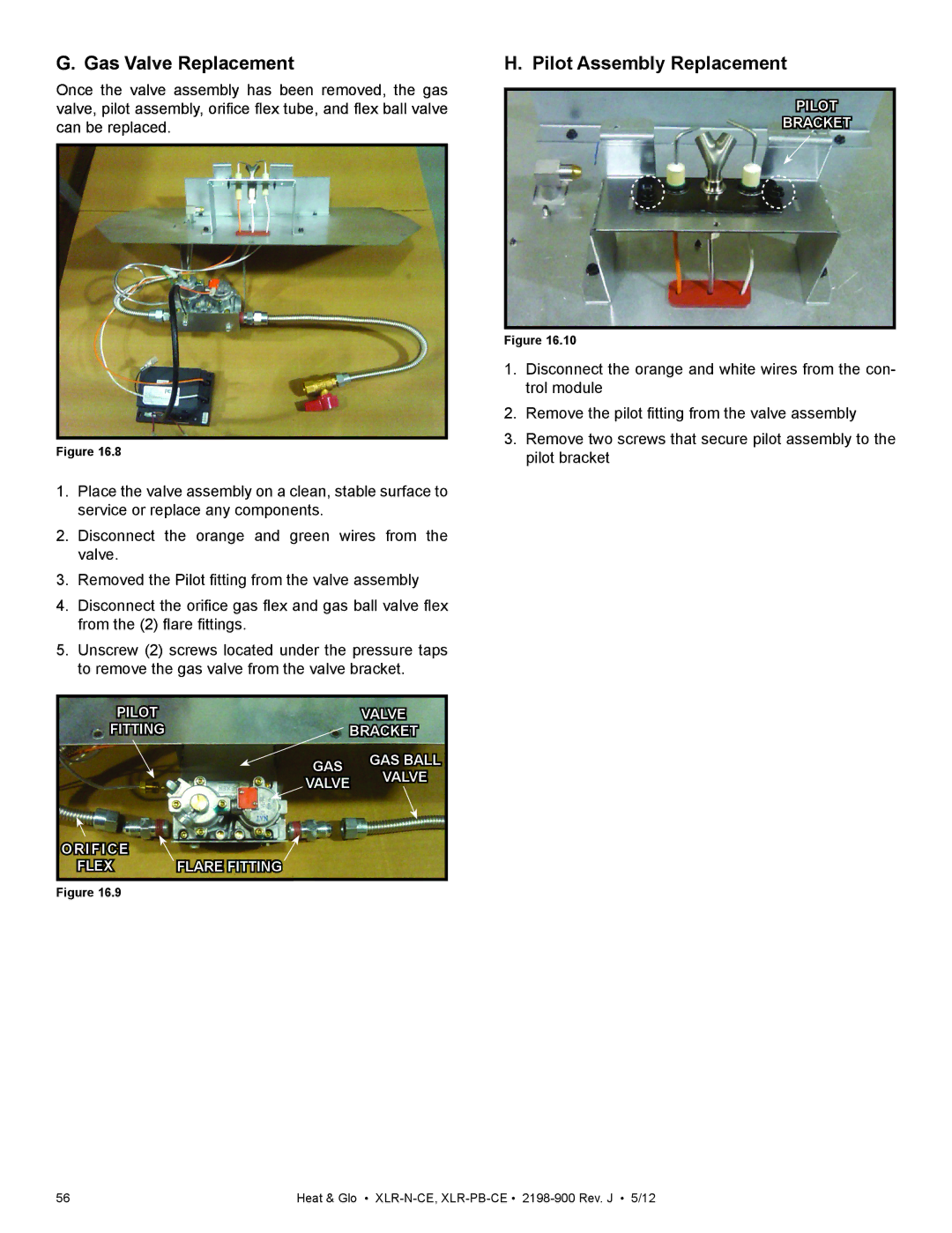
H. Pilot Assembly Replacement
A. Appliance Dimension Diagram
17 Reference Materials
Location
Centimeters
B. Vent Components Diagrams
Figure 17.2 Vent Components
35,2 cm
24,1 cm
B. Vent Components Diagrams continued
SLP-45- 45 Elbow
SLP90- 90 Elbow
Effective
B. Vent Components Diagrams continued
SLK-SNKD
SLP-CCS-BK
SLP-TVHW
B. Vent Components Diagrams continued
20,3 cm Heat Shield 38,4 cm
30,5 cm
Effective
C. Service Parts
XLR-N-CE, XLR-PB-CE
Landscape DV Appliance
DESCRIPTION
Service Parts
#14 Valve Assembly
XLR-N-CE, XLR-PB-CE
DESCRIPTION
C. Service Parts List
XLR-N-CE, XLR-PB-CE
DESCRIPTION
COMMENTS
D. Contact Information
NOTICE