F. Access Through the Valve Assembly
The lower access cover panel is removable if finishing material has not been previously installed.
Remove media tray, burner assembly, and base pan. To access components:
1.Remove eleven screws around perimeter of valve as- sembly that secure valve plate to the firebox bottom. See Figure 16.5.
2.Lift the valve assembly from the back so that the gas valve can clear the valve plate hole in the bottom the firebox. See Figure 16.6.
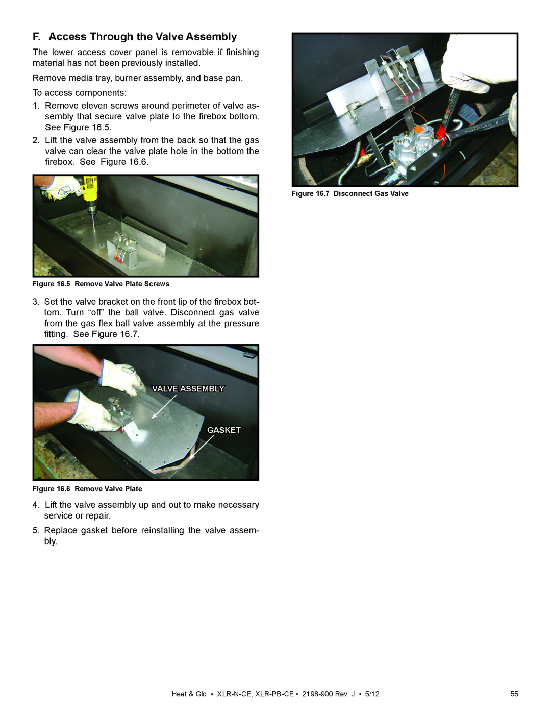
Figure 16.7 Disconnect Gas Valve
Figure 16.5 Remove Valve Plate Screws
3.Set the valve bracket on the front lip of the firebox bot- tom. Turn “off” the ball valve. Disconnect gas valve from the gas flex ball valve assembly at the pressure fitting. See Figure 16.7.
VALVE ASSEMBLY
GASKET
Figure 16.6 Remove Valve Plate
4.Lift the valve assembly up and out to make necessary service or repair.
5.Replace gasket before reinstalling the valve assem- bly.
Heat & Glo • | 55 |