D. Electrical Service and Repair
WARNING! Risk of Shock! Label all wires prior to dis- connection when servicing controls. Wiring errors can cause improper and dangerous operation. Verify proper operation after servicing.
WARNING! Risk of Shock! Replace damaged wire with type 105° C rated wire. Wire must have high temperature insulation.
F. Blower
An optional fan and auxilliary box are available for this appliance. Refer to instructions provided with
Use of the fan requires that the Junction cord (factory in- stalled) be connected to 220/240 VAC service before per- manently enclosing the heater. The service cord is found on the right exterior side of the unit. See Figure 12.3 for wire connection detail.
E. Junction Cord Information
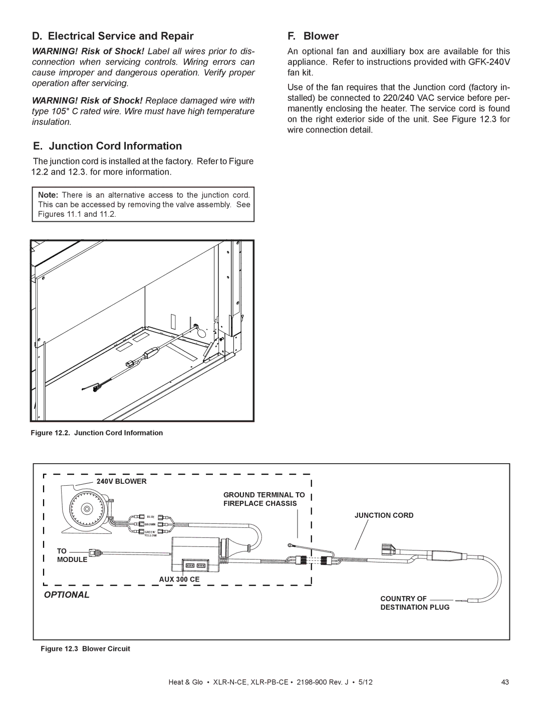
The junction cord is installed at the factory. Refer to Figure 12.2 and 12.3. for more information.
Note: There is an alternative access to the junction cord.
This can be accessed by removing the valve assembly. See
Figures 11.1 and 11.2.
Figure 12.2. Junction Cord Information
240V BLOWER |
|
| GROUND TERMINAL TO |
| FIREPLACE CHASSIS |
BLUE | JUNCTION CORD |
BROWN |
|
GREEN/ |
|
YELLOW |
|
TO |
|
MODULE |
|
| AUX 300 CE |
OPTIONAL | COUNTRY OF |
| DESTINATION PLUG |
Figure 12.3 Blower Circuit
Heat & Glo • | 43 |