H. Install Vertical Termination Cap
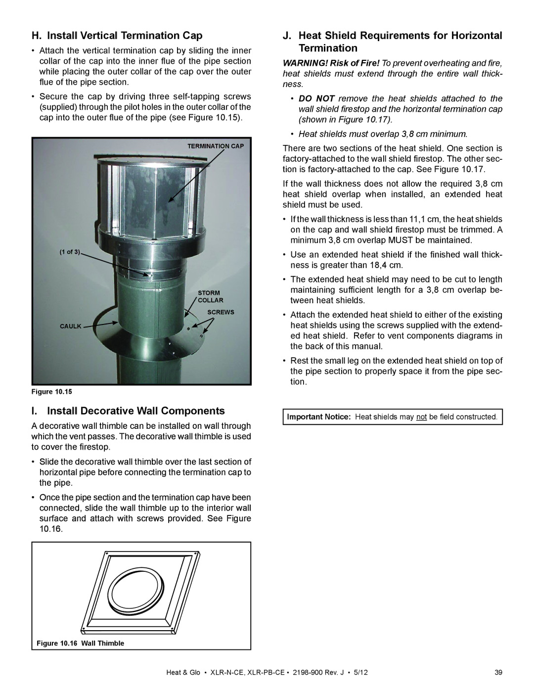
•Attach the vertical termination cap by sliding the inner collar of the cap into the inner flue of the pipe section while placing the outer collar of the cap over the outer flue of the pipe section.
•Secure the cap by driving three
TERMINATION CAP
(1 of 3)
STORM
COLLAR
SCREWS
CAULK ![]()
Figure 10.15
I. Install Decorative Wall Components
A decorative wall thimble can be installed on wall through which the vent passes. The decorative wall thimble is used to cover the firestop.
•Slide the decorative wall thimble over the last section of horizontal pipe before connecting the termination cap to the pipe.
•Once the pipe section and the termination cap have been connected, slide the wall thimble up to the interior wall surface and attach with screws provided. See Figure 10.16.
Figure 10.16 Wall Thimble
J.Heat Shield Requirements for Horizontal Termination
WARNING! Risk of Fire! To prevent overheating and fire, heat shields must extend through the entire wall thick- ness.
•DO NOT remove the heat shields attached to the wall shield firestop and the horizontal termination cap (shown in Figure 10.17).
•Heat shields must overlap 3,8 cm minimum.
There are two sections of the heat shield. One section is
If the wall thickness does not allow the required 3,8 cm heat shield overlap when installed, an extended heat shield must be used.
•If the wall thickness is less than 11,1 cm, the heat shields on the cap and wall shield firestop must be trimmed. A minimum 3,8 cm overlap MUST be maintained.
•Use an extended heat shield if the finished wall thick- ness is greater than 18,4 cm.
•The extended heat shield may need to be cut to length maintaining sufficient length for a 3,8 cm overlap be- tween heat shields.
•Attach the extended heat shield to either of the existing heat shields using the screws supplied with the extend- ed heat shield. Refer to vent components diagrams in the back of this manual.
•Rest the small leg on the extended heat shield on top of the pipe section to properly space it from the pipe sec- tion.
Important Notice: Heat shields may not be field constructed.
Heat & Glo • | 39 |