B. Vent Components Diagrams (continued)
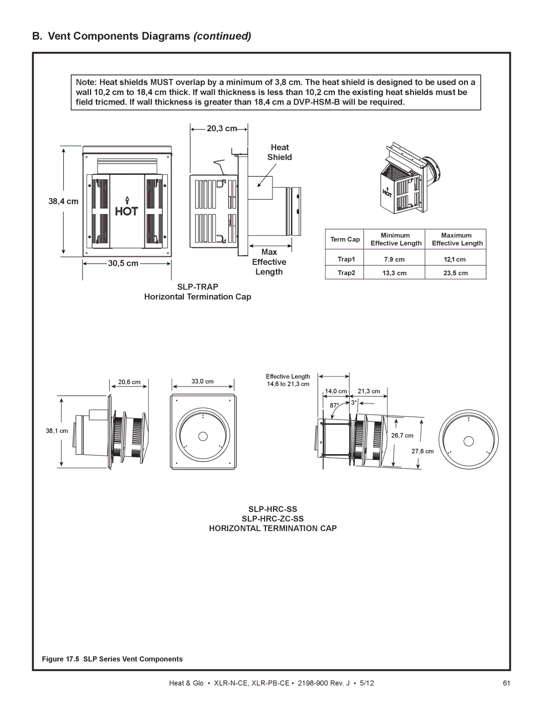
Note: Heat shields MUST overlap by a minimum of 3,8 cm. The heat shield is designed to be used on a wall 10,2 cm to 18,4 cm thick. If wall thickness is less than 10,2 cm the existing heat shields must be field tricmed. If wall thickness is greater than 18,4 cm a
![]() 20,3 cm
20,3 cm![]()
Heat
Shield
38,4 cm
| Max |
30,5 cm | Effective |
Length
SLP-TRAP
Horizontal Termination Cap
Term Cap | Minimum | Maximum | |
Effective Length | Effective Length | ||
| |||
|
|
| |
Trap1 | 7.9 cm | 12,1 cm | |
Trap2 | 13,3 cm | 23,5 cm |
20,6 cm
38,1 cm
33,0 cm
Effective Length 14,6 to 21,3 cm
14,0 cm 21,3 cm
87° ![]() 3°
3°![]()
![]()
26,7 cm
27,6 cm
SLP-HRC-SS
SLP-HRC-ZC-SS
HORIZONTAL TERMINATION CAP
Figure 17.5 SLP Series Vent Components
Heat & Glo • | 61 |