D. Disassemble Vent Sections
•Rotate either section (see Figure 10.7) so the seams on both pipe sections are aligned as shown in Figure 10.8.
•Pull carefully to separate the pieces of pipe.
Figure 10.7 Rotate Seams for Disassembly
Figure 10.8 Align and Disassemble Vent Sections
E. Install Decorative Ceiling Components
A decorative ceiling thimble can be installed on a flat ceil- ing through which the vent passes. The decorative ceiling thimble is used to cover the firestop.
• Seal the gap between the vent pipe and firestop using high temperature (150 ºC minimum continuous exposure rating) silicone to prevent cold air infiltration.
•Install the decorative ceiling thimble by sliding it up to the ceiling and attaching it using the provided screws.
A decorative cathedral ceiling support box can be installed on a cathedral ceiling through which the vent passes.
•Use a
•Remove shingles or other roof covering as necessary to cut the rectangular hole for the support box. Cut the hole 3 mm larger than the support box outline.
•Lower the support box through the hole in the roof until its
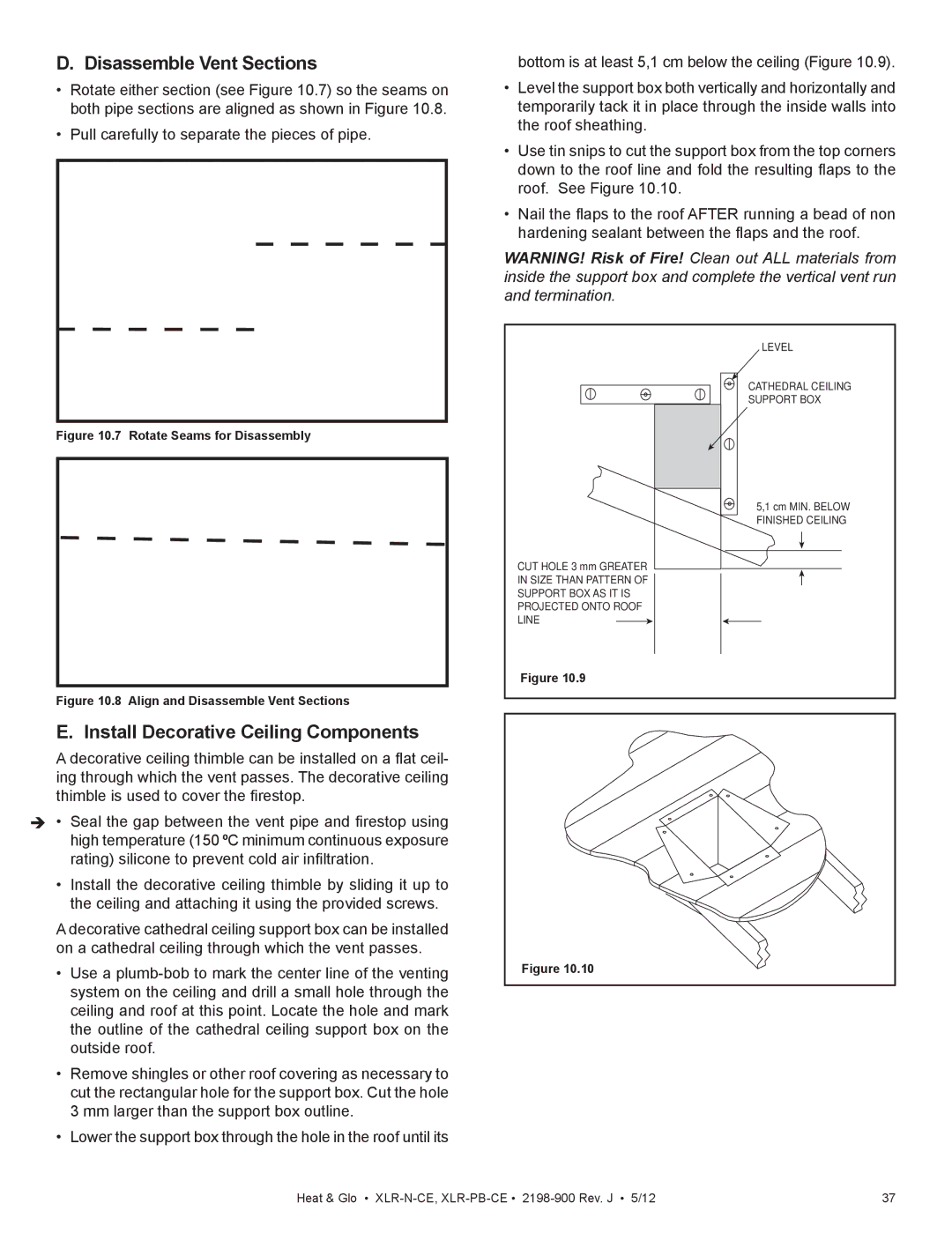
bottom is at least 5,1 cm below the ceiling (Figure 10.9).
•Level the support box both vertically and horizontally and temporarily tack it in place through the inside walls into the roof sheathing.
•Use tin snips to cut the support box from the top corners down to the roof line and fold the resulting flaps to the roof. See Figure 10.10.
•Nail the flaps to the roof AFTER running a bead of non hardening sealant between the flaps and the roof.
WARNING! Risk of Fire! Clean out ALL materials from inside the support box and complete the vertical vent run and termination.
LEVEL
CATHEDRAL CEILING
SUPPORT BOX
5,1 cm MIN. BELOW FINISHED CEILING
CUT HOLE 3 mm GREATER
IN SIZE THAN PATTERN OF
SUPPORT BOX AS IT IS
PROJECTED ONTO ROOF
LINE
Figure 10.9
Figure 10.10 |
Heat & Glo • | 37 |