IF YOU SUSPECT A PROBLEM
Heat Alarms may not operate properly because of a
•If you experience frequent
•If the alarm sounds when no smoke is visible, try cleaning or relocating the Heat Alarm. The cover may be dirty.
•If the alarm does not sound during testing, make sure it is receiving AC power from the household current.
RECOMMENDED LOCATIONS FOR HEAT ALARMS
In Single-Family Residences.
For minimum coverage, BRK Brands, Inc. recommends you install Heat Alarms in any area not suitable for smoke alarms such as garages, kitchens, utility/laundry rooms, furnace rooms and crawl spaces. Install where tempera- tures normally remain between
For National Fire Protection Association (NFPA) information, see “Agency Placement Recommendations for Heat Alarms and Smoke Alarms.”
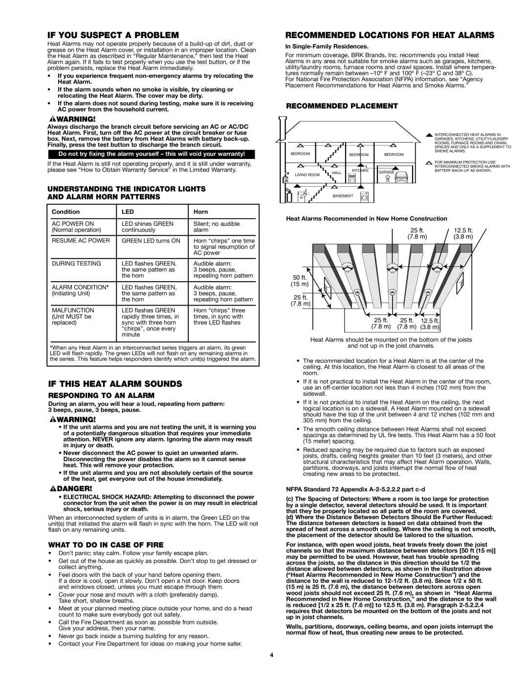
RECOMMENDED PLACEMENT
Always discharge the branch circuit before servicing an AC or AC/DC Heat Alarm. First, turn off the AC power at the circuit breaker or fuse box. Next, remove the battery from Heat Alarms with battery
Do not try fixing the alarm yourself – this will void your warranty!
If the Heat Alarm is still not operating properly, and it is still under warranty, please see “How to Obtain Warranty Service” in the Limited Warranty.
UNDERSTANDING THE INDICATOR LIGHTS AND ALARM HORN PATTERNS
BEDROOM |
| BEDROOM | BEDROOM |
| HALL | KITCHEN | GARAGE |
LIVING ROOM |
| ||
|
|
| |
| BASEMENT |
| |
INTERCONNECTED HEAT ALARMS IN GARAGES, KITCHENS, UTILITY/LAUNDRY ROOMS, FURNACE ROOMS AND CRAWL SPACES AND ONLY AS A SUPPLEMENT TO SMOKE ALARMS.
FOR MAXIMUM PROTECTION USE INTERCONNECTED SMOKE ALARMS WITH BATTERY
| Condition | LED | Horn |
|
|
|
|
|
|
| AC POWER ON | LED shines GREEN | Silent; no audible |
|
| (Normal operation) | continuously | alarm |
|
|
|
|
|
|
| RESUME AC POWER | GREEN LED turns ON | Horn “chirps” one time |
|
|
|
| to signal resumption of |
|
|
|
| AC power |
|
| DURING TESTING | LED flashes GREEN, | Audible alarm: |
|
|
| the same pattern as | 3 beeps, pause, |
|
|
| the horn | repeating horn pattern |
|
|
|
|
|
|
| ALARM CONDITION* | LED flashes GREEN, | Audible alarm: |
|
| (Initiating Unit) | the same pattern as | 3 beeps, pause, |
|
|
| the horn | repeating horn pattern |
|
|
|
|
|
|
| MALFUNCTION | LED flashes GREEN | Horn “chirps” three |
|
| (Unit MUST be | rapidly three times, in | times, in sync with |
|
| replaced) | sync with three horn | three LED flashes |
|
|
| “chirps”, once every |
|
|
|
| minute |
|
|
|
|
|
|
|
*When any Heat Alarm in an interconnected series triggers an alarm, its green LED will flash rapidly. The green LEDs will not flash on any remaining alarms in the series. This feature helps responders identify which unit(s) triggered the alarm.
IF THIS HEAT ALARM SOUNDS
RESPONDING TO AN ALARM
During an alarm, you will hear a loud, repeating horn pattern: 3 beeps, pause, 3 beeps, pause.
•If the unit alarms and you are not testing the unit, it is warning you of a potentially dangerous situation that requires your immediate attention. NEVER ignore any alarm. Ignoring the alarm may result in injury or death.
•Never disconnect the AC power to quiet an unwanted alarm. Disconnecting the power disables the alarm so it cannot sense heat. This will remove your protection.
•If the unit alarms and you are not absolutely certain of the source of the heat, get everyone out of the house immediately.
•ELECTRICAL SHOCK HAZARD: Attempting to disconnect the power connector from the unit when the power is on may result in electrical shock, serious injury or death.
When an interconnected system of units is in alarm, the Green LED on the unit(s) that initiated the alarm will flash in sync with the horn. The LED will not flash on any remaining units.
WHAT TO DO IN CASE OF FIRE
•Don’t panic; stay calm. Follow your family escape plan.
•Get out of the house as quickly as possible. Don’t stop to get dressed or collect anything.
•Feel doors with the back of your hand before opening them.
If a door is cool, open it slowly. Don’t open a hot door. Keep doors and windows closed, unless you must escape through them.
•Cover your nose and mouth with a cloth (preferably damp). Take short, shallow breaths.
•Meet at your planned meeting place outside your home, and do a head count to make sure everybody got out safely.
•Call the Fire Department as soon as possible from outside. Give your address, then your name.
•Never go back inside a burning building for any reason.
•Contact your Fire Department for ideas on making your home safer.
Heat Alarms Recommended in New Home Construction
25 ft. | 12.5 ft. |
(7.8 m) | (3.8 m) |
50 ft. |
|
|
(15 m) |
|
|
25 ft. |
|
|
(7.8 m) |
|
|
25 ft. | 25 ft. | 12.5 ft. |
(7.8 m) | (7.8 m) | (3.8 m) |
Heat Alarms should be mounted on the bottom of the joists
and not up in the joist channels.
•The recommended location for a Heat Alarm is at the center of the ceiling. At this location, the Heat Alarm is closest to all areas of the room.
•If it is not practical to install the Heat Alarm in the center of the room, use an
•If it is not practical to install the Heat Alarm on the ceiling, the next logical location is on a sidewall. A Heat Alarm mounted on a sidewall should have the top of the unit between 4 and 12 inches (102 mm and 305 mm) from the ceiling.
•The smooth ceiling distance between Heat Alarms shall not exceed spacings as determined by UL fire tests. This Heat Alarm has a 50 foot (15 meter) spacing.
•Reduced spacing may be required due to factors such as exposed joists, drafts, ceiling heights greater than 10 feet (3 meters), and other structural characteristics that may affect Heat Alarm operation. Walls, partitions, doorways, and joists interrupt the normal flow of heat creating new areas to be protected.
NFPA Standard 72 Appendix
(c)The Spacing of Detectors: Where a room is too large for protection by a single detector, several detectors should be used. It is important that they be properly located so all parts of the room are covered.
(d)Where the Distance Between Detectors Should Be Further Reduced: The distance between detectors is based on data obtained from the spread of heat across a smooth ceiling. Where the ceiling is not smooth, the placement of the detector should be tailored to the situation.
For instance, with open wood joists, heat travels freely down the joist channels so that the maximum distance between detectors [50 ft (15 m)] may be permitted to be used. However, heat has trouble spreading across the joists, so the distance in this direction should be 1/2 the distance allowed between detectors, as shown in the illustration above (“Heat Alarms Recommended in New Home Construction”) and the distance to the wall is reduced to
(15 m) is 25 ft. (7.6 m), the distance between detectors across open wood joists should not exceed 25 ft. (7.6 m), as shown in “Heat Alarms Recommended in New Home Construction,” and the distance to the wall is reduced [1/2 x 25 ft. (7.6 m)] to 12.5 ft. (3.8 m). Paragraph
Walls, partitions, doorways, ceiling beams, and open joists interrupt the normal flow of heat, thus creating new areas to be protected.
4