HOW THIS HEAT ALARM WORKS
This Heat Alarm monitors the air and when heat reaches the sensor, it alarms. The unit will alarm when the temperature reaches a fixed 135º F (57º C).
Heat Alarms are intended for use as supplemental safety devices with Smoke Alarms. Heat Alarms are designed for use in areas where Smoke Alarms cannot be installed due to temperature and environmental conditions, as in unheated garages and crawl spaces. A Heat Alarm can only give early warning of a developing fire if it is properly installed and maintained and located where heat can reach it. The unit will not sense gas, smoke or flame. Heat Alarms cannot prevent or extinguish fires.
This Heat Alarm is approved for use in
3
1
4
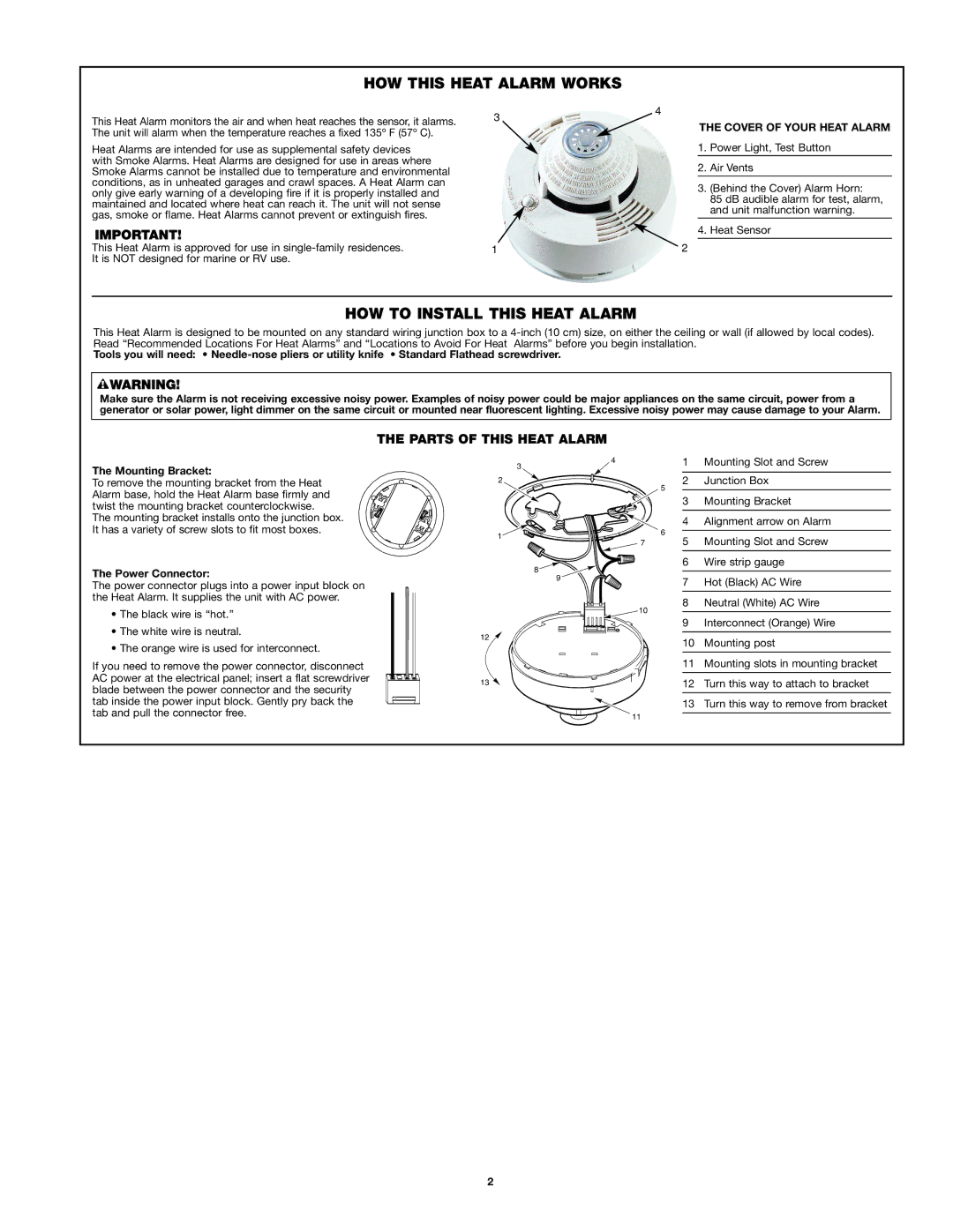
THE COVER OF YOUR HEAT ALARM
1.Power Light, Test Button
2.Air Vents
3.(Behind the Cover) Alarm Horn:
85 dB audible alarm for test, alarm, and unit malfunction warning.
4.Heat Sensor
2
HOW TO INSTALL THIS HEAT ALARM
This Heat Alarm is designed to be mounted on any standard wiring junction box to a
Tools you will need: •
Make sure the Alarm is not receiving excessive noisy power. Examples of noisy power could be major appliances on the same circuit, power from a generator or solar power, light dimmer on the same circuit or mounted near fluorescent lighting. Excessive noisy power may cause damage to your Alarm.
THE PARTS OF THIS HEAT ALARM
The Mounting Bracket:
To remove the mounting bracket from the Heat Alarm base, hold the Heat Alarm base firmly and twist the mounting bracket counterclockwise.
The mounting bracket installs onto the junction box. It has a variety of screw slots to fit most boxes.
The Power Connector:
The power connector plugs into a power input block on the Heat Alarm. It supplies the unit with AC power.
•The black wire is “hot.”
•The white wire is neutral.
•The orange wire is used for interconnect.
If you need to remove the power connector, disconnect AC power at the electrical panel; insert a flat screwdriver blade between the power connector and the security tab inside the power input block. Gently pry back the tab and pull the connector free.
4 | 1 | Mounting Slot and Screw | |
3 |
|
| |
2 | 2 | Junction Box | |
| 5 |
| |
| 3 | Mounting Bracket | |
| 4 | Alignment arrow on Alarm | |
1 | 6 |
| |
5 | Mounting Slot and Screw | ||
7 | |||
8 | 6 | Wire strip gauge | |
|
| ||
9 | 7 | Hot (Black) AC Wire | |
| |||
10 | 8 | Neutral (White) AC Wire | |
|
| ||
| 9 | Interconnect (Orange) Wire | |
12 | 10 | Mounting post | |
| |||
| 11 | Mounting slots in mounting bracket | |
13 | 12 | Turn this way to attach to bracket | |
| 13 | Turn this way to remove from bracket | |
11 |
|
|
2