The Chimney Adapter Kit is a listed alternative venting system for these furnaces. See the kit instructions for complete details.
This furnace is permitted to be vented into a clay tile-lined masonry chimney that is exposed to the outdoors below the roof line, provided:
1.Vent connector is Type-B double-wall, and
2.This furnace is common vented with at least 1 draft hood- equipped appliance, and
3.The combined appliance input rating is less than the max- imum capacity given in Table 8, and
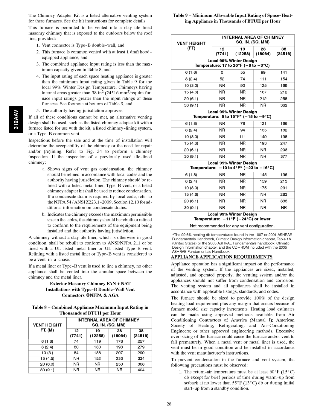
4.The input rating of each space heating appliance is greater than the minimum input rating given in Table 9 for the local 99% Winter Design Temperature. Chimneys having internal areas greater than 38 in2 (24516 mm2)require fur- nace input ratings greater than the input ratings of these furnaces. See footnote at bottom of Table 9, and
5.The authority having jurisdiction approves.
If all of these conditions cannot be met, an alternative venting design shall be used, such as the listed chimney adapter kit with a furnace listed for use with the kit, a listed chimney-lining system, or a Type-B common vent.
Inspections before the sale and at the time of installation will determine the acceptability of the chimney or the need for repair and/or (re)lining. Refer to Fig. 34 to perform a chimney inspection. If the inspection of a previously used tile-lined chimney:
a. Shows signs of vent gas condensation, the chimney should be relined in accordance with local codes and the authority having jurisdiction. The chimney should be re- lined with a listed metal liner, Type-B vent, or a listed chimney adapter kit shall be used to reduce condensation. If a condensate drain is required by local code, refer to the NFPA 54 / ANSI Z223.1-2009, Section 12.10 for ad- ditional information on condensate drains.
b.Indicates the chimney exceeds the maximum permissible size in the tables, the chimney should be rebuilt or relined to conform to the requirements of the equipment being installed and the authority having jurisdiction.
A chimney without a clay tile liner, which is otherwise in good condition, shall be rebuilt to conform to ANSI/NFPA 211 or be lined with a UL listed metal liner or UL listed Type-B vent. Relining with a listed metal liner or Type-B vent is considered to be a vent-in-a-chase.
If a metal liner or Type-B vent is used to line a chimney, no other appliance shall be vented into the annular space between the chimney and the metal liner.
Exterior Masonry Chimney FAN + NAT
Installations with Type-B Double-Wall Vent
Connectors ENFPA & AGA
Table 8 – Combined Appliance Maximum Input Rating in
Thousands of BTUH per Hour
| INTERNAL AREA OF CHIMNEY |
VENT HEIGHT | | SQ. IN. (SQ. MM) | |
FT. (M) | | | | |
12 | 19 | 28 | 38 |
| (7741) | (12258) | (18064) | (24516) |
6 (1.8) | 74 | 119 | 178 | 257 |
8 (2.4) | 80 | 130 | 193 | 279 |
10 (3.) | 84 | 138 | 207 | 299 |
15 (4.5) | NR | 152 | 233 | 334 |
20 (6.0) | NR | NR | 250 | 368 |
30 (9.1) | NR | NR | NR | 404 |
Table 9 – Minimum Allowable Input Rating of Space-Heat-
ing Appliance in Thousands of BTUH per Hour
| | | INTERNAL AREA OF CHIMNEY |
VENT HEIGHT | | | SQ. IN. (SQ. MM) | |
(FT) | | | | | | |
| 12 | 19 | 28 | | 38 |
| | | (7741) | (12258) | (18064) | | (24516) |
| | | | | | | |
| | Local 99% Winter Design | |
| Temperature: 17 to 26_F (---8 to ---3_C) | |
| | | | | |
6 (1.8) | | 0 | 55 | 99 | | 141 |
| | | | | | |
8 (2.4) | | 52 | 74 | 111 | | 154 |
| | | | | | | |
10 | (3.0) | | NR | 90 | 125 | | 169 |
| | | | | | | |
15 | (4.6) | | NR | NR | 167 | | 212 |
| | | | | | | |
20 | (6.1) | | NR | NR | 212 | | 258 |
| | | | | | | |
30 | (9.1) | | NR | NR | NR | | 362 |
| | | | | | | |
| | Local 99% Winter Design | |
| Temperature: 5 to 16_F* (---15 to ---9_C) | |
| | | | | | |
6 (1.8) | | NR | 78 | 121 | | 166 |
| | | | | | |
8 (2.4) | | NR | 94 | 135 | | 182 |
| | | | | | | |
10 | (3.0) | | NR | 111 | 149 | | 198 |
| | | | | | | |
15 | (4.6) | | NR | NR | 193 | | 247 |
| | | | | | | |
20 | (6.1) | | NR | NR | NR | | 293 |
| | | | | | | |
30 | (9.1) | | NR | NR | NR | | 377 |
| | | | | | | |
| | Local 99% Winter Design | |
| Temperature: ---10 to 4_F* (---23 to ---16_C) | |
| | | | | | |
6 (1.8) | | NR | NR | 145 | | 196 |
| | | | | | |
8 (2.4) | | NR | NR | 159 | | 213 |
| | | | | | | |
10 | (3.0) | | NR | NR | 175 | | 231 |
| | | | | | | |
15 | (4.6) | | NR | NR | NR | | 283 |
| | | | | | | |
20 | (6.1) | | NR | NR | NR | | 333 |
| | | | | | | |
30 | (9.1) | | NR | NR | NR | | NR |
| | | | | | | |
| | Local 99% Winter Design | |
| Temperature: ---11_F (---24_C) or lower | |
| | |
| Not recommended for any vent configuration. | |
| | | | | | | |
*The 99.6% heating db temperatures found in the 1997 or 2001 ASHRAE Fundamentals Handbook, Climatic Design Information chapter, Table 1A (United States) or the 2005 ASHRAE Fundamentals handbook, Climatic Design Information chapter, and the CD ---ROM included with the 2005 ASHRAE Fundamentals Handbook.
APPLIANCE APPLICATION REQUIREMENTS
Appliance operation has a significant impact on the performance of the venting system. If the appliances are sized, installed, adjusted, and operated properly, the venting system and/or the appliances should not suffer from condensation and corrosion. The venting system and all appliances shall be installed in accordance with applicable listings, standards, and codes.
The furnace should be sized to provide 100% of the design heating load requirement plus any margin that occurs because of furnace model size capacity increments. Heating load estimates can be made using approved methods available from Air Conditioning Contractors of America (Manual J); American Society of Heating, Refrigerating, and Air-Conditioning Engineers; or other approved engineering methods. Excessive over-sizing of the furnace could cause the furnace and/or vent to fail prematurely. When a metal vent or metal liner is used, the vent must be in good condition and be installed in accordance with the vent manufacturer’s instructions.
To prevent condensation in the furnace and vent system, the following precautions must be observed:
1.The return-air temperature must be at least 60_F (15_C) db except for brief periods of time during warm-up from setback at no lower than 55_F (13_C) db or during initial start-up from a standby condition.