box or inlet pipe, but can be removed without removing either. After removing screw, slide igniter and bracket toward outside of burner box and pull straight out.
CAUTION: The igniter is fragile. DO NOT allow it to hit the side of the burner box opening while removing or replacing it.
b.Inspect igniter for a white area indicating a crack may be present. If found, replace igniter.
NOTE: A small crack cannot be seen on a new igniter. After a period of operation, a white area will be visible around the crack.
c. If replacement is required, replace igniter on igniter bracket external to furnace to avoid damage as the silicon portion is very brittle and will easily crack or shatter.
d. To remove igniter from igniter bracket, remove screw holding igniter ceramic block to bracket and pull ce- ramic block out of bracket.
6.To replace igniter/igniter assembly, reverse items 5a through 5d.
7.Reconnect igniter wire connection.
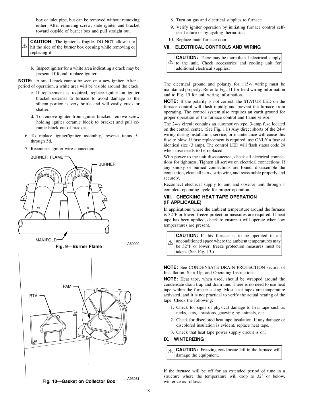
BURNER FLAME
BURNER
8.Turn on gas and electrical supplies to furnace.
9.Verify igniter operation by initiating furnace control self- test feature or by cycling thermostat.
10.Replace main furnace door.
VII. ELECTRICAL CONTROLS AND WIRING
CAUTION: There may be more than 1 electrical supply to the unit. Check accessories and cooling unit for additional electrical supplies.
The electrical ground and polarity for
NOTE: If the polarity is not correct, the STATUS LED on the furnace control will flash rapidly and prevent the furnace from operating. The control system also requires an earth ground for proper operation of the furnace control and flame sensor.
The
With power to the unit disconnected, check all electrical connec- tions for tightness. Tighten all screws on electrical connections. If any smoky or burned connections are found, disassemble the connection, clean all parts, strip wire, and reassemble properly and securely.
Reconnect electrical supply to unit and observe unit through 1 complete operating cycle for proper operation.
VIII. CHECKING HEAT TAPE OPERATION (IF APPLICABLE)
In applications where the ambient temperature around the furnace is 32°F or lower, freeze protection measures are required. If heat tape has been applied, check to ensure it will operate when low temperatures are present.
MANIFOLD![]()
Fig. 9—Burner Flame
PAM
RTV
A89020
CAUTION: If this furnace is to be operated in an unconditioned space where the ambient temperatures may be 32°F or lower, freeze protection measures must be taken. (See Fig. 13.)
NOTE: See CONDENSATE DRAIN PROTECTION section of Installation,
NOTE: Heat tape, when used, should be wrapped around the condensate drain trap and drain line. There is no need to use heat tape within the furnace casing. Most heat tapes are temperature activated, and it is not practical to verify the actual heating of the tape. Check the following:
1.Check for signs of physical damage to heat tape such as nicks, cuts, abrasions, gnawing by animals, etc.
2.Check for discolored heat tape insulation. If any damage or discolored insulation is evident, replace heat tape.
3.Check that heat tape power supply circuit is on.
IX. WINTERIZING
CAUTION: Freezing condensate left in the furnace will damage the equipment.
Fig. 10—Gasket on Collector Box
A93081
If the furnace will be off for an extended period of time in a structure where the temperature will drop to 32° or below, winterize as follows: