|
|
|
|
|
| FIELD | |
|
|
|
|
|
| FIELD | |
|
|
|
|
|
| FACTORY | |
|
|
|
|
|
| FACTORY | |
|
|
| NOTE 2 |
| THERMOSTAT |
| |
|
| FIVE WIRE |
| W C R | G Y | ||
|
|
| TERMINALS | ||||
|
|
|
|
| |||
|
|
|
|
|
| DISCONNECT | |
|
|
|
|
|
|
| |
|
|
|
|
| 208/230- OR | ||
BLOWER DOOR SWITCH |
|
|
|
| |||
|
|
|
| ||||
|
|
|
|
|
|
| |
|
|
|
|
|
|
| THREE |
BLK | BLK |
|
| W |
|
| PHASE |
|
|
|
|
| |||
|
|
|
|
|
| ||
WHT | WHT |
| C | R |
|
|
|
| O |
|
|
|
| ||
|
|
| N |
|
|
| |
| GND | GND | T |
|
|
| SINGLE |
AUXILIARY | R | G |
|
| PHASE | ||
O |
|
|
|
| |||
| SUPPLIED | L | COM |
|
| GND | |
DISCONNECT |
|
| NOTE 1 |
| CONDENSING | ||
|
|
|
| Y/Y2 |
| UNIT |
|
|
|
|
|
|
|
| |
|
|
|
| TWO |
| ||
|
| TERMINAL |
| WIRE |
| ||
|
|
| BLOCK |
|
|
| |
|
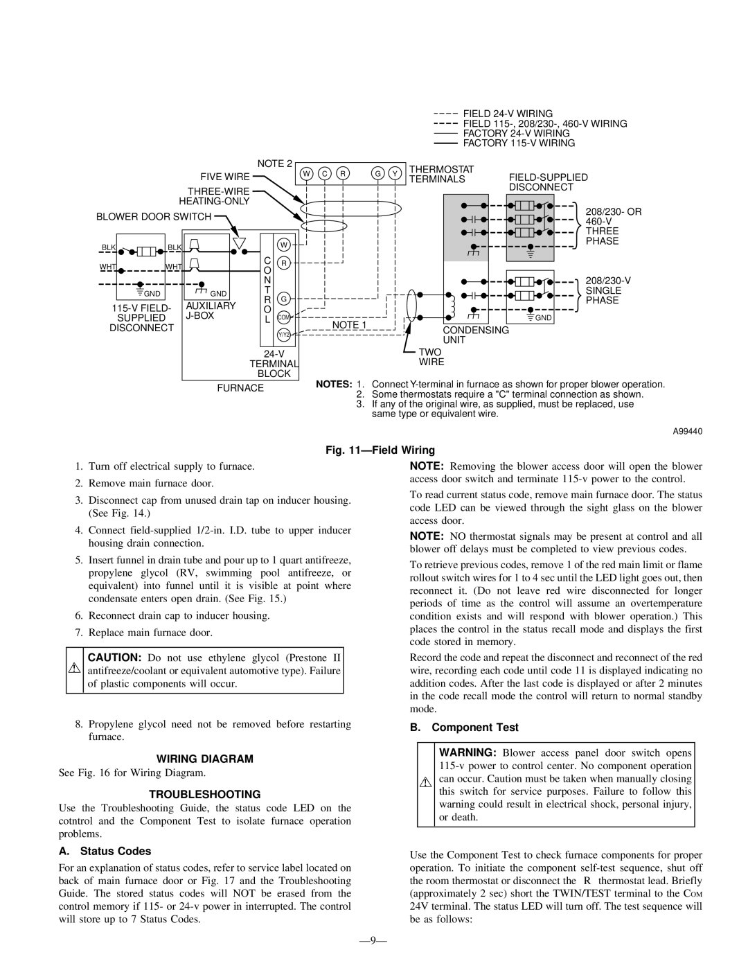
| FURNACE | NOTES: 1. Connect | ||||
|
| 2. | Some thermostats require a "C" terminal connection as shown. | ||||
|
|
|
| ||||
3. If any of the original wire, as supplied, must be replaced, use same type or equivalent wire.
A99440
Fig. 11—Field Wiring
1.Turn off electrical supply to furnace.
2.Remove main furnace door.
3.Disconnect cap from unused drain tap on inducer housing. (See Fig. 14.)
4.Connect
5.Insert funnel in drain tube and pour up to 1 quart antifreeze, propylene glycol (RV, swimming pool antifreeze, or equivalent) into funnel until it is visible at point where condensate enters open drain. (See Fig. 15.)
6.Reconnect drain cap to inducer housing.
7.Replace main furnace door.
NOTE: Removing the blower access door will open the blower access door switch and terminate
To read current status code, remove main furnace door. The status code LED can be viewed through the sight glass on the blower access door.
NOTE: NO thermostat signals may be present at control and all blower off delays must be completed to view previous codes.
To retrieve previous codes, remove 1 of the red main limit or flame rollout switch wires for 1 to 4 sec until the LED light goes out, then reconnect it. (Do not leave red wire disconnected for longer periods of time as the control will assume an overtemperature condition exists and will respond with blower operation.) This places the control in the status recall mode and displays the first code stored in memory.
CAUTION: Do not use ethylene glycol (Prestone II antifreeze/coolant or equivalent automotive type). Failure of plastic components will occur.
8.Propylene glycol need not be removed before restarting furnace.
Record the code and repeat the disconnect and reconnect of the red wire, recording each code until code 11 is displayed indicating no addition codes. After the last code is displayed or after 2 minutes in the code recall mode the control will return to normal standby mode.
B. Component Test
WIRING DIAGRAM
See Fig. 16 for Wiring Diagram.
TROUBLESHOOTING
Use the Troubleshooting Guide, the status code LED on the cotntrol and the Component Test to isolate furnace operation problems.
WARNING: Blower access panel door switch opens
A. Status Codes
For an explanation of status codes, refer to service label located on back of main furnace door or Fig. 17 and the Troubleshooting Guide. The stored status codes will NOT be erased from the control memory if 115- or
Use the Component Test to check furnace components for proper operation. To initiate the component