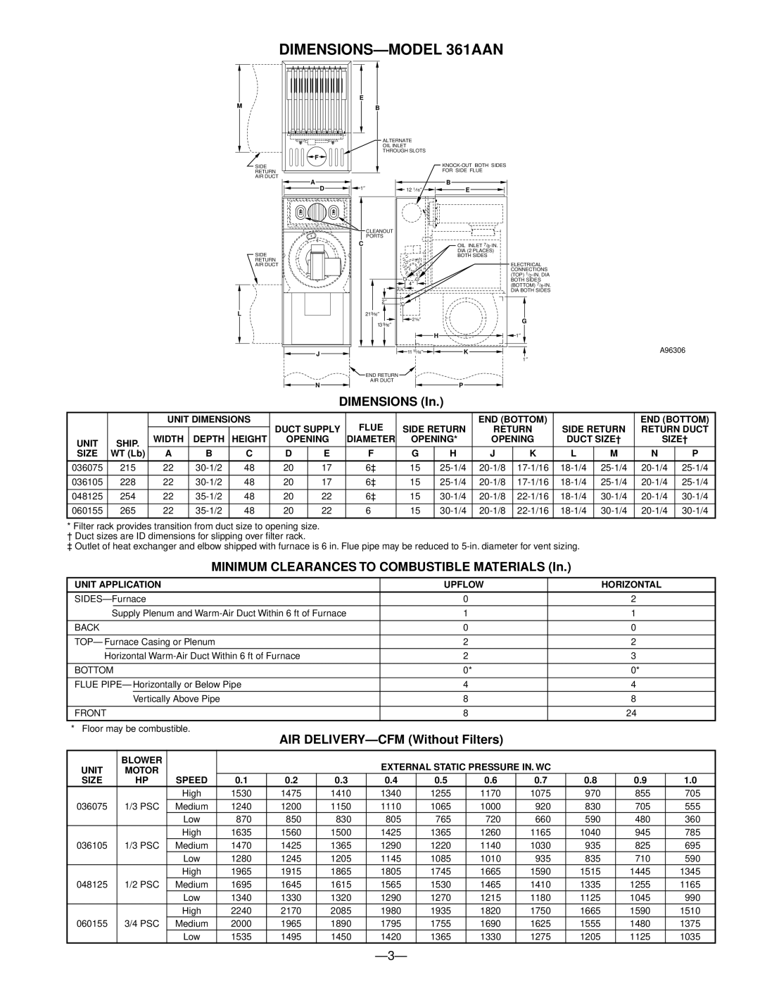
DIMENSIONS—MODEL 361AAN


E


M


B


ALTERNATE


OIL INLET


THROUGH SLOTS


F


SIDE


KNOCK-OUT BOTH SIDES

RETURN


FOR SIDE FLUE

AIR DUCT


A


B

D

1

12 116

E


CLEANOUT


PORTS


C


OIL INLET 7/8-IN.

SIDE


DIA (2 PLACES)


BOTH SIDES

RETURN


ELECTRICAL

AIR DUCT


CONNECTIONS


(TOP) 1/2-IN. DIA


4

BOTH SIDES

1

(BOTTOM) 7/8-IN.

3 ⁄16

DIA BOTH SIDES


2

L


21916

2

916

G

13 916


H 1

J

N

111516

END RETURN

AIR DUCT

K

P

A96306

1

DIMENSIONS (In.)


UNIT DIMENSIONS


FLUE


END (BOTTOM)


END (BOTTOM)


DUCT SUPPLY

SIDE RETURN

RETURN

SIDE RETURN

RETURN DUCT


UNIT

SHIP.

WIDTH

DEPTH

HEIGHT

OPENING

DIAMETER

OPENING*

OPENING

DUCT SIZE†

SIZE†


SIZE

WT (Lb)

A

B

C

D

E

F

G

H

J

K

L

M

N

P


036075

215

22

30-1/2

48

20

17

6‡

15

25-1/4

20-1/8

17-1/16

18-1/4

25-1/4

20-1/4

25-1/4


036105

228

22

30-1/2

48

20

17

6‡

15

25-1/4

20-1/8

17-1/16

18-1/4

25-1/4

20-1/4

25-1/4


048125

254

22

35-1/2

48

20

22

6‡

15

30-1/4

20-1/8

22-1/16

18-1/4

30-1/4

20-1/4

30-1/4


060155

265

22

35-1/2

48

20

22

6

15

30-1/4

20-1/8

22-1/16

18-1/4

30-1/4

20-1/4

30-1/4


*Filter rack provides transition from duct size to opening size.

† Duct sizes are ID dimensions for slipping over filter rack.

‡ Outlet of heat exchanger and elbow shipped with furnace is 6 in. Flue pipe may be reduced to 5-in. diameter for vent sizing.

MINIMUM CLEARANCES TO COMBUSTIBLE MATERIALS (In.)

UNIT APPLICATION


UPFLOW


HORIZONTAL


SIDES—Furnace


0


2


Supply Plenum and Warm-Air Duct Within 6 ft of Furnace


1


1


BACK


0


0


TOP— Furnace Casing or Plenum


2


2


Horizontal Warm-Air Duct Within 6 ft of Furnace


2


3


BOTTOM


0*


0*


FLUE PIPE— Horizontally or Below Pipe


4


4


Vertically Above Pipe


8


8


FRONT


8


24


* Floor may be combustible.


AIR DELIVERY—CFM (Without Filters)


BLOWER


EXTERNAL STATIC PRESSURE IN. WC


UNIT


MOTOR


SIZE


HP

SPEED


0.1

0.2

0.3


0.4

0.5


0.6

0.7


0.8


0.9

1.0


High


1530

1475

1410


1340

1255


1170

1075

970


855

705

036075


1/3 PSC

Medium


1240

1200

1150


1110

1065


1000

920

830


705

555


Low


870

850

830


805

765


720

660

590


480

360


High


1635

1560

1500


1425

1365


1260

1165

1040


945

785

036105


1/3 PSC

Medium


1470

1425

1365


1290

1220


1140

1030

935


825

695


Low


1280

1245

1205


1145

1085


1010

935

835


710

590


High


1965

1915

1865


1805

1745


1665

1590

1515


1445

1345

048125


1/2 PSC

Medium


1695

1645

1615


1565

1530


1465

1410

1335


1255

1165


Low


1340

1330

1320


1290

1270


1215

1180

1125


1045

990


High


2240

2170

2085


1980

1935


1820

1750

1665


1590

1510

060155


3/4 PSC

Medium


2000

1965

1890


1795

1755


1690

1625

1555


1480

1375


Low


1535

1495

1450


1420

1365


1330

1275

1205


1125

1035

—3—

Page 3
Image 3
Bryant 363AAP 361AAN manual DIMENSIONS-MODEL 361AAN

363AAP 361AAN specifications

The Bryant 363AAP and 361AAN are standout models in the HVAC industry, offering high efficiency and reliability for residential heating and cooling needs. Designed with advanced technologies, these units are tailored to provide optimal comfort while minimizing energy consumption and operating costs.

The Bryant 363AAP is a high-efficiency air conditioning unit that boasts a seasonal energy efficiency ratio (SEER) rating of up to 16. This impressive rating ensures that homeowners can enjoy both a comfortable indoor environment and lower energy bills. Additionally, the unit features a two-stage compressor that allows for better temperature regulation, ensuring consistent cooling and enhanced humidity control.

On the other hand, the Bryant 361AAN is a gas furnace that delivers outstanding performance with an Annual Fuel Utilization Efficiency (AFUE) rating of up to 95%. This means that 95% of the fuel consumed is converted into usable heat, providing efficient and cost-effective heating solutions. The 361AAN is equipped with a variable-speed blower motor that optimizes airflow and noise levels, ensuring a quiet and comfortable atmosphere year-round.

Both models incorporate innovative technologies designed to improve indoor air quality and system reliability. The inclusion of Puron refrigerant in the Bryant 363AAP not only aids in enhancing the unit's efficiency but also makes it environmentally friendly by eliminating ozone-depleting substances. Meanwhile, the 361AAN’s compatibility with the Infinity control system allows homeowners to manage their heating and cooling from virtually anywhere, providing added convenience and control through Wi-Fi connectivity.

The robust construction of these models ensures durability and longevity. Featuring galvanized steel cabinets with a powder-coated finish, both units are designed to withstand the elements and resist corrosion. The Bryant 363AAP and 361AAN also come equipped with advanced sound-dampening technology, ensuring quieter operation that will not disturb daily life.

In summary, the Bryant 363AAP and 361AAN stand out for their high efficiency, innovative technologies, and durable construction, making them ideal choices for homeowners seeking reliable heating and cooling solutions. With their commitment to comfort and efficiency, these models set a high standard in the HVAC market.