TABLE 10—BURNER INPUT AND NOZZLE SIZE
FURNACE | FIRING | RIELLO OIL BURNER | PUMP | ||
INPUT | RATE | No. 40 | Nozzle | PRESSURE | |
(BTUH) | GAL/HR (US) | Series Model | (PSIG) | ||
| |||||
70,000 | 0.50 | F3 | 0.40 - 70A | 160 | |
91,000 | 0.65 | F3 | 0.50 - 70W | 170 | |
105,000 | 0.75 | F3 | 0.65 - 70W | 135 | |
119,000 | 0.85 | F5 | 0.75 - 70B | 130 | |
140,000 | 1.00 | F5 | 0.85 - 70W | 140 | |
154,000 | 1.10 | F5 | 1.00 - 70W | 125 | |
|
|
|
|
| |
d. If purging takes longer than 15 sec and no flame has been established, burner stops. Push reset button on front of primary control to restart burner.
e.For detailed information on operation of primary control, refer to instructions included with furnace.
After all the setup procedures mentioned above have been com- pleted, the burner should be allowed to operate and an inspection mirror should be used to observe the flame pattern at tip of nozzle. Any irregularities such as burning to 1 side or pulsating flame patterns should be corrected by changing nozzle.
III. FAN ADJUSTMENT CHECK
This furnace is equipped with a
WARNING: When operating furnace in heating mode, static pressure and temperature rise
Adjust fan speed ACCORDING TO OIL INPUT SELECTED so that temperature rise is within rise range specified on rating plate. (See Table 11.) Consult wiring diagram for speed changes on
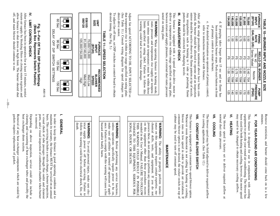
To adjust fan off time, set DIP switches on control board to obtain desired timing. (See Fig. 5.)
TABLE 11—SPEED SELECTION
|
| UNIT |
|
| FURNACE |
|
| RECOMMENDED | |||||||||||||
|
|
|
|
| INPUT |
|
| BLOWER | |||||||||||||
|
| SIZE |
|
|
|
|
| ||||||||||||||
|
|
|
|
| (BTUH) |
|
| SPEED | |||||||||||||
|
|
|
|
|
|
|
|
|
|
| |||||||||||
036105/ | 70,000/119,000 |
|
|
|
| ||||||||||||||||
91,000/140,000 |
|
|
|
| |||||||||||||||||
060120 |
|
|
|
| |||||||||||||||||
|
|
|
|
|
|
|
|
|
|
|
|
|
|
|
| ||||||
105,000/154,000 |
|
|
|
| High | ||||||||||||||||
|
|
|
|
|
|
|
|
|
| ||||||||||||
|
|
|
|
|
|
|
|
|
|
|
|
|
|
|
|
|
|
|
|
|
|
|
|
|
|
|
|
|
|
|
|
|
|
|
|
|
|
|
|
|
|
|
|
|
|
|
|
|
|
|
|
|
|
|
|
|
|
|
|
|
|
|
|
|
|
|
|
|
|
|
|
|
|
|
|
|
|
|
|
|
|
|
|
|
|
|
|
Remove restriction, and burner should come back on in a few minutes.
V. FOR YEAR-ROUND AIR CONDITIONING
This furnace is designed for use in conjunction with cooling equipment to provide
VI. HEATING
The blower speed is factory set to deliver required airflow at normal duct static pressure.
VII. COOLING
The blower speed may be field adjusted to deliver required airflow for cooling application. (See Table 12.)
VIII. CONSTANT BLOWER SWITCH
This furnace is equipped with a constant
MAINTENANCE
WARNING: The ability to properly perform mainte- nance on this equipment requires certain expertise, me- chanical skills, tools, and equipment. If you do not possess these, do not attempt to perform any maintenance on this equipment other than those procedures recom- mended in the User’s Manual. FAILURE TO FOLLOW THIS WARNING COULD RESULT IN POSSIBLE DAMAGE TO THIS EQUIPMENT, SERIOUS PER- SONAL INJURY, OR DEATH.
WARNING: Before performing any service functions, unless operations specifically require power to be on, make sure all utilities are turned off upstream of appli- ance. Failure to comply with this warning will cause a fire hazard and/or bodily harm.
WARNING: To avoid personal injury, make sure elec- trical supply power is off before servicing. Failure to follow this warning could lead to electrical shock, fire, or death.
|
|
|
|
|
|
|
|
|
|
|
|
|
| 1 | 2 |
| 1 | 2 |
| 1 | 2 |
| 1 | 2 |
|
| 60 Sec |
| 90 Sec |
| 120 Sec |
| 150 Sec | |||||
|
|
| DELAY OFF DIP SWITCH SETTINGS |
|
| |||||||
|
|
|
|
|
|
|
|
|
|
|
|
|
A95115
Fig. 5—Fan Off Time DIP Switch Settings (Black Box Represents Switch Position)
IV. LIMIT CONTROL CHECK
After furnace has been in operation for at least 15 minutes, restrict
I. GENERAL
In order to keep this furnace in good operating condition and to maintain its warranty, the furnace MUST be serviced on an annual basis. This servicing includes a nozzle change, a burner inspection, a visual check of tube passages through flue outlet and cleanout ports, and a visual inspection of combustion chamber when burner is removed.
Depending on above inspection, service could also include a cleaning and vacuuming of heat exchanger tubes and possibly the heat exchanger drum section.
Removal of any heat exchanger components which are sealed by gaskets requires replacement of gasket.