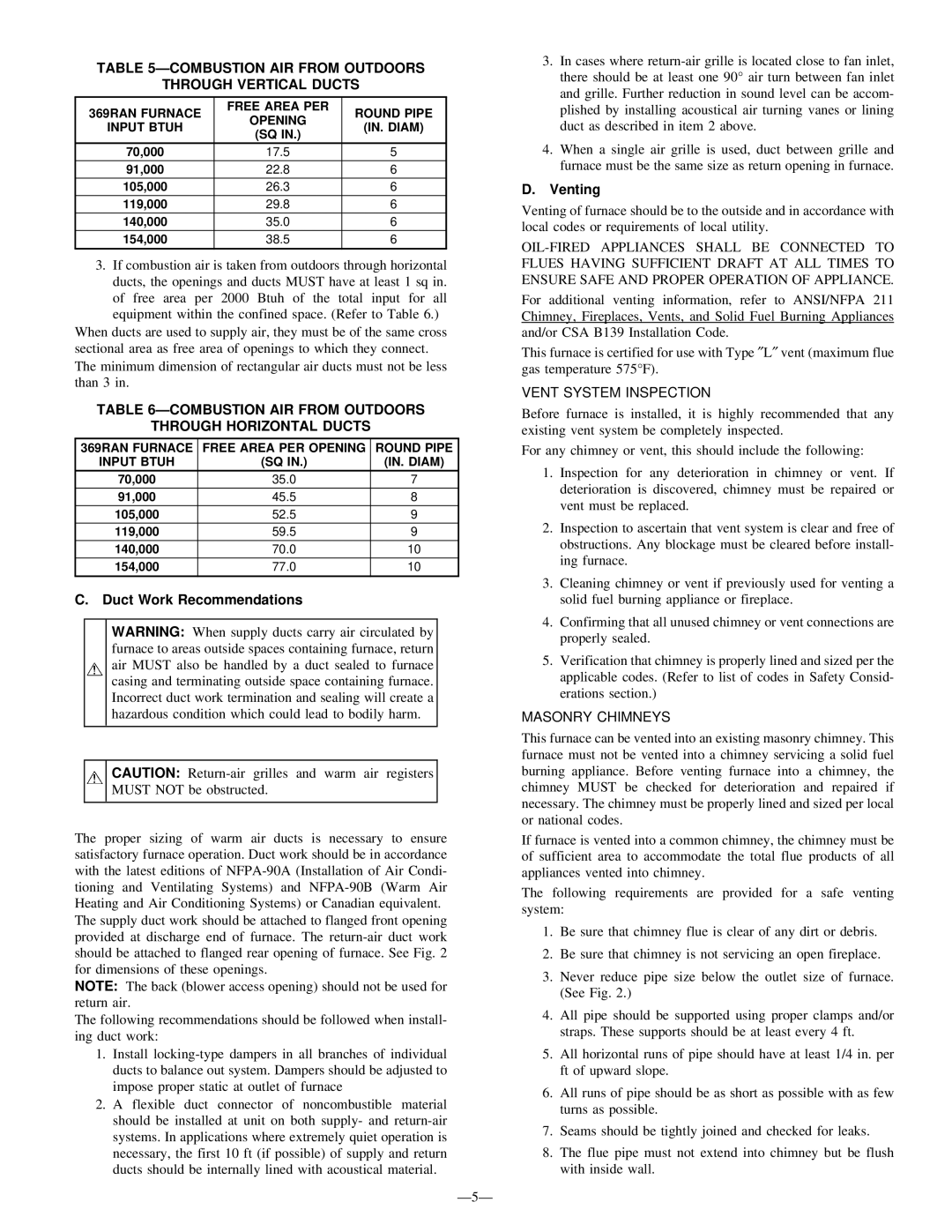
TABLE 5—COMBUSTION AIR FROM OUTDOORS
THROUGH VERTICAL DUCTS
369RAN FURNACE | FREE AREA PER | ROUND PIPE | |
OPENING | |||
INPUT BTUH | (IN. DIAM) | ||
(SQ IN.) | |||
|
| ||
70,000 | 17.5 | 5 | |
91,000 | 22.8 | 6 | |
105,000 | 26.3 | 6 | |
119,000 | 29.8 | 6 | |
140,000 | 35.0 | 6 | |
154,000 | 38.5 | 6 | |
|
|
|
3.If combustion air is taken from outdoors through horizontal ducts, the openings and ducts MUST have at least 1 sq in. of free area per 2000 Btuh of the total input for all equipment within the confined space. (Refer to Table 6.)
When ducts are used to supply air, they must be of the same cross sectional area as free area of openings to which they connect. The minimum dimension of rectangular air ducts must not be less than 3 in.
TABLE 6—COMBUSTION AIR FROM OUTDOORS
THROUGH HORIZONTAL DUCTS
369RAN FURNACE | FREE AREA PER OPENING | ROUND PIPE |
INPUT BTUH | (SQ IN.) | (IN. DIAM) |
70,000 | 35.0 | 7 |
91,000 | 45.5 | 8 |
105,000 | 52.5 | 9 |
119,000 | 59.5 | 9 |
140,000 | 70.0 | 10 |
154,000 | 77.0 | 10 |
C. Duct Work Recommendations
WARNING: When supply ducts carry air circulated by furnace to areas outside spaces containing furnace, return air MUST also be handled by a duct sealed to furnace casing and terminating outside space containing furnace. Incorrect duct work termination and sealing will create a hazardous condition which could lead to bodily harm.
CAUTION:
The proper sizing of warm air ducts is necessary to ensure satisfactory furnace operation. Duct work should be in accordance with the latest editions of
The supply duct work should be attached to flanged front opening provided at discharge end of furnace. The
NOTE: The back (blower access opening) should not be used for return air.
The following recommendations should be followed when install- ing duct work:
1.Install
2.A flexible duct connector of noncombustible material should be installed at unit on both supply- and
3.In cases where
4.When a single air grille is used, duct between grille and furnace must be the same size as return opening in furnace.
D.Venting
Venting of furnace should be to the outside and in accordance with local codes or requirements of local utility.
For additional venting information, refer to ANSI/NFPA 211 Chimney, Fireplaces, Vents, and Solid Fuel Burning Appliances and/or CSA B139 Installation Code.
This furnace is certified for use with Type ″ L″ vent (maximum flue gas temperature 575°F).
VENT SYSTEM INSPECTION
Before furnace is installed, it is highly recommended that any existing vent system be completely inspected.
For any chimney or vent, this should include the following:
1.Inspection for any deterioration in chimney or vent. If deterioration is discovered, chimney must be repaired or vent must be replaced.
2.Inspection to ascertain that vent system is clear and free of obstructions. Any blockage must be cleared before install- ing furnace.
3.Cleaning chimney or vent if previously used for venting a solid fuel burning appliance or fireplace.
4.Confirming that all unused chimney or vent connections are properly sealed.
5.Verification that chimney is properly lined and sized per the applicable codes. (Refer to list of codes in Safety Consid- erations section.)
MASONRY CHIMNEYS
This furnace can be vented into an existing masonry chimney. This furnace must not be vented into a chimney servicing a solid fuel burning appliance. Before venting furnace into a chimney, the chimney MUST be checked for deterioration and repaired if necessary. The chimney must be properly lined and sized per local or national codes.
If furnace is vented into a common chimney, the chimney must be of sufficient area to accommodate the total flue products of all appliances vented into chimney.
The following requirements are provided for a safe venting system:
1.Be sure that chimney flue is clear of any dirt or debris.
2.Be sure that chimney is not servicing an open fireplace.
3.Never reduce pipe size below the outlet size of furnace. (See Fig. 2.)
4.All pipe should be supported using proper clamps and/or straps. These supports should be at least every 4 ft.
5.All horizontal runs of pipe should have at least 1/4 in. per ft of upward slope.
6.All runs of pipe should be as short as possible with as few turns as possible.
7.Seams should be tightly joined and checked for leaks.
8.The flue pipe must not extend into chimney but be flush with inside wall.