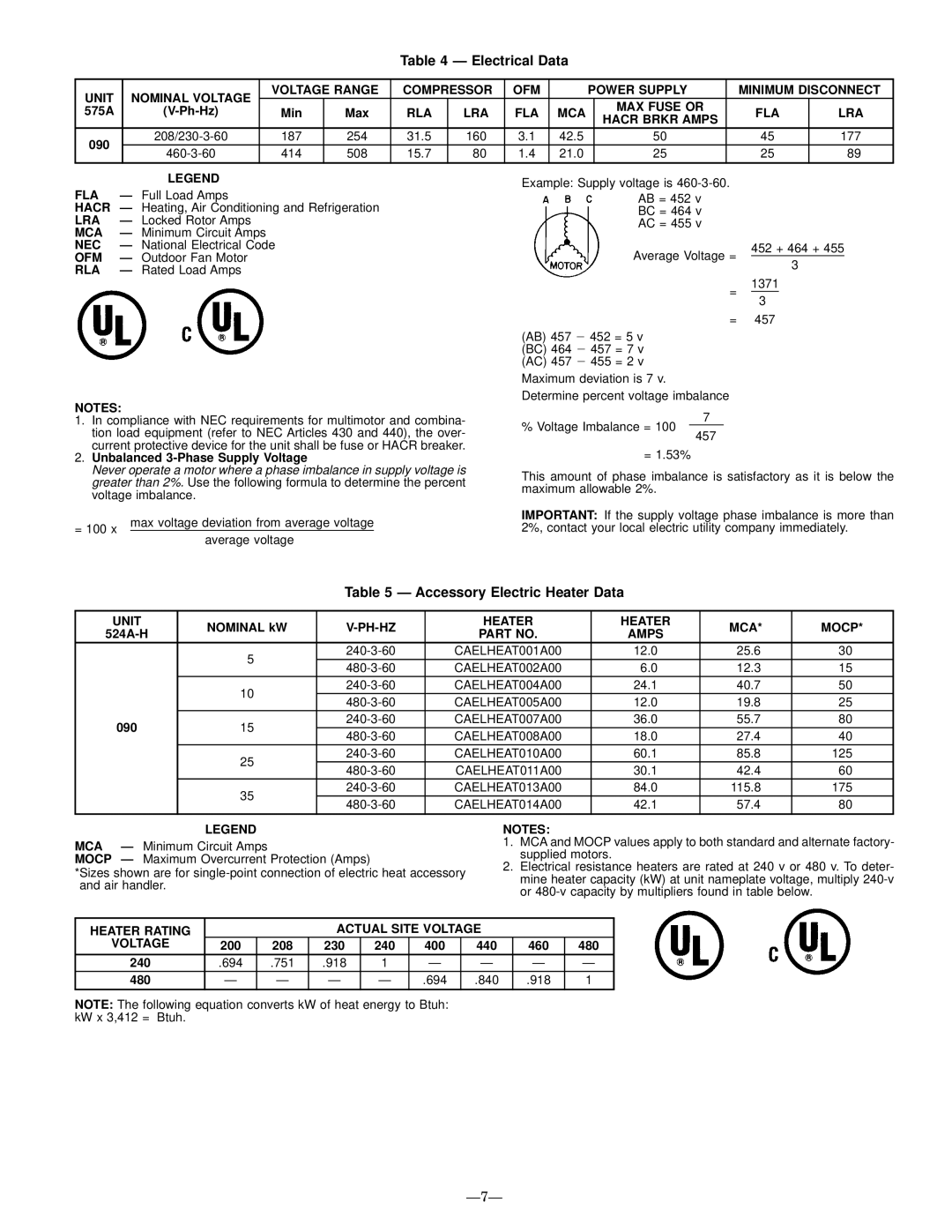
Table 4 Ð Electrical Data

UNIT

NOMINAL VOLTAGE

VOLTAGE RANGE

COMPRESSOR

OFM


POWER SUPPLY

MINIMUM DISCONNECT

575A

(V-Ph-Hz)

Min

Max

RLA

LRA

FLA

MCA


MAX FUSE OR

FLA

LRA


HACR BRKR AMPS


090

208/230-3-60

187

254

31.5

160

3.1

42.5


50

45

177

460-3-60

414

508

15.7

80

1.4

21.0


25

25

89


LEGEND

FLA

Ð Full Load Amps

HACR Ð Heating, Air Conditioning and Refrigeration

LRA

Ð Locked Rotor Amps

MCA

Ð Minimum Circuit Amps

NEC

Ð National Electrical Code

OFM

Ð Outdoor Fan Motor

RLA

Ð Rated Load Amps

Example: Supply voltage is 460-3-60.

AB = 452 v BC = 464 v AC = 455 v

Average Voltage =

452 + 464 + 455

3

=

1371

3

NOTES:

1.In compliance with NEC requirements for multimotor and combina- tion load equipment (refer to NEC Articles 430 and 440), the over- current protective device for the unit shall be fuse or HACR breaker.

2.Unbalanced 3-Phase Supply Voltage

Never operate a motor where a phase imbalance in supply voltage is greater than 2%. Use the following formula to determine the percent voltage imbalance.

= 100 x

max voltage deviation from average voltage

average voltage


= 457

(AB) 457 2 452 = 5 v (BC) 464 2 457 = 7 v

(AC) 457 2 455 = 2 v Maximum deviation is 7 v. Determine percent voltage imbalance

7

% Voltage Imbalance = 100

457

= 1.53%

This amount of phase imbalance is satisfactory as it is below the maximum allowable 2%.

IMPORTANT: If the supply voltage phase imbalance is more than 2%, contact your local electric utility company immediately.

Table 5 Ð Accessory Electric Heater Data

UNIT

NOMINAL kW

V-PH-HZ

HEATER

HEATER

MCA*

MOCP*

524A-H

PART NO.

AMPS


5

240-3-60

CAELHEAT001A00

12.0

25.6

30


480-3-60

CAELHEAT002A00

6.0

12.3

15


10

240-3-60

CAELHEAT004A00

24.1

40.7

50


480-3-60

CAELHEAT005A00

12.0

19.8

25


090

15

240-3-60

CAELHEAT007A00

36.0

55.7

80

480-3-60

CAELHEAT008A00

18.0

27.4

40


25

240-3-60

CAELHEAT010A00

60.1

85.8

125


480-3-60

CAELHEAT011A00

30.1

42.4

60


35

240-3-60

CAELHEAT013A00

84.0

115.8

175


480-3-60

CAELHEAT014A00

42.1

57.4

80


LEGEND

MCA

Ð Minimum Circuit Amps

MOCP

Ð Maximum Overcurrent Protection (Amps)

*Sizes shown are for single-point connection of electric heat accessory and air handler.

NOTES:

1.MCA and MOCP values apply to both standard and alternate factory- supplied motors.

2.Electrical resistance heaters are rated at 240 v or 480 v. To deter- mine heater capacity (kW) at unit nameplate voltage, multiply 240-v or 480-v capacity by multipliers found in table below.

HEATER RATING


ACTUAL SITE VOLTAGE


VOLTAGE

200

208

230

240

400


440

460

480

240

.694

.751

.918

1

Ð


Ð

Ð

Ð

480

Ð

Ð

Ð

Ð

.694

.

840

.918

1

NOTE: The following equation converts kW of heat energy to Btuh: kW x 3,412 = Btuh.

Ð7Ð

Page 7
Image 7
Bryant 575A installation instructions Electrical Data, Accessory Electric Heater Data, Ð7Ð

575A specifications

The Bryant 575A is a prominent model in Bryant's lineup of heating, ventilation, and air conditioning (HVAC) systems, known for its reliability and efficiency. Designed with advanced technologies and innovative features, the Bryant 575A is an excellent choice for both residential and light commercial applications.

One of the standout features of the Bryant 575A is its impressive energy efficiency. With a Seasonal Energy Efficiency Ratio (SEER) rating that significantly surpasses the minimum standards, the 575A helps homeowners reduce their energy bills while maintaining optimal comfort levels. The system employs variable-speed technology, allowing for precise temperature control and enhanced humidity management. This ensures that the indoor environment remains comfortable year-round, regardless of outdoor conditions.

Incorporating advanced refrigerant management, the Bryant 575A utilizes environmentally friendly R-410A refrigerant. This refrigerant not only minimizes ozone depletion potential but also enhances the overall performance of the system, allowing for efficient heat exchange and quick temperature adjustments. The system's efficiency is further optimized by its multi-stage cooling capabilities, which allow it to adapt to varying cooling loads and maintain consistent indoor temperatures.

The Bryant 575A is built with reliability in mind, featuring durable construction and quality components designed to withstand the rigors of daily use. Its compact design makes it easy to install in various settings, and its low profile ensures it can fit into tight spaces without compromising performance. Additionally, the system is designed for quiet operation, making it an ideal choice for residential areas where noise may be a concern.

Another significant aspect of the Bryant 575A is its compatibility with Bryant's intelligent thermostat technology. The system can seamlessly integrate with smart home setups, allowing homeowners to control their HVAC systems remotely via smartphone apps or home automation systems. This convenience not only enhances user experience but also contributes to energy savings by allowing for more precise control over heating and cooling schedules.

In summary, the Bryant 575A embodies the blend of efficiency, reliability, and advanced technology, making it a top choice for those seeking a high-performance HVAC solution. With features designed to optimize comfort and energy use, the Bryant 575A stands out as a strong contender in the competitive HVAC market.