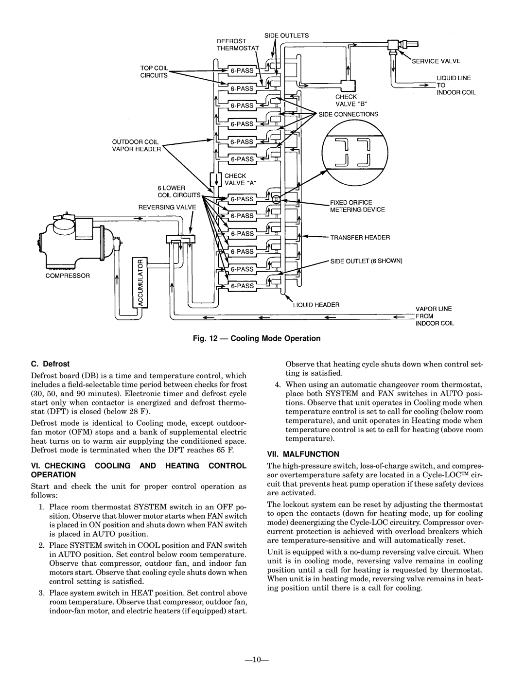
Fig. 12 Ð Cooling Mode Operation

C. Defrost

Defrost board (DB) is a time and temperature control, which includes a ®eld-selectable time period between checks for frost (30, 50, and 90 minutes). Electronic timer and defrost cycle start only when contactor is energized and defrost thermo- stat (DFT) is closed (below 28 F).

Defrost mode is identical to Cooling mode, except outdoor- fan motor (OFM) stops and a bank of supplemental electric heat turns on to warm air supplying the conditioned space. Defrost mode is terminated when the DFT reaches 65 F.

VI. CHECKING COOLING AND HEATING CONTROL OPERATION

Start and check the unit for proper control operation as follows:

1.Place room thermostat SYSTEM switch in an OFF po- sition. Observe that blower motor starts when FAN switch is placed in ON position and shuts down when FAN switch is placed in AUTO position.

2.Place SYSTEM switch in COOL position and FAN switch in AUTO position. Set control below room temperature. Observe that compressor, outdoor fan, and indoor fan motors start. Observe that cooling cycle shuts down when control setting is satis®ed.

3.Place system switch in HEAT position. Set control above room temperature. Observe that compressor, outdoor fan, indoor-fan motor, and electric heaters (if equipped) start.

Observe that heating cycle shuts down when control set- ting is satis®ed.

4.When using an automatic changeover room thermostat, place both SYSTEM and FAN switches in AUTO posi- tions. Observe that unit operates in Cooling mode when temperature control is set to call for cooling (below room temperature), and unit operates in Heating mode when temperature control is set to call for heating (above room temperature).

VII. MALFUNCTION

The high-pressure switch, loss-of-charge switch, and compres- sor overtemperature safety are located in a Cycle-LOC™ cir- cuit that prevents heat pump operation if these safety devices are activated.

The lockout system can be reset by adjusting the thermostat to open the contacts (down for heating mode, up for cooling mode) deenergizing the Cycle-LOC circuitry. Compressor over- current protection is achieved with overload breakers which are temperature-sensitive and will automatically reset.

Unit is equipped with a no-dump reversing valve circuit. When unit is in cooling mode, reversing valve remains in cooling position until a call for heating is requested by thermostat. When unit is in heating mode, reversing valve remains in heat- ing position until there is a call for cooling.

Ð10Ð

Page 10
Image 10
Bryant 575A installation instructions VI. Checking Cooling and Heating Control Operation, VII. Malfunction

575A specifications

The Bryant 575A is a prominent model in Bryant's lineup of heating, ventilation, and air conditioning (HVAC) systems, known for its reliability and efficiency. Designed with advanced technologies and innovative features, the Bryant 575A is an excellent choice for both residential and light commercial applications.

One of the standout features of the Bryant 575A is its impressive energy efficiency. With a Seasonal Energy Efficiency Ratio (SEER) rating that significantly surpasses the minimum standards, the 575A helps homeowners reduce their energy bills while maintaining optimal comfort levels. The system employs variable-speed technology, allowing for precise temperature control and enhanced humidity management. This ensures that the indoor environment remains comfortable year-round, regardless of outdoor conditions.

Incorporating advanced refrigerant management, the Bryant 575A utilizes environmentally friendly R-410A refrigerant. This refrigerant not only minimizes ozone depletion potential but also enhances the overall performance of the system, allowing for efficient heat exchange and quick temperature adjustments. The system's efficiency is further optimized by its multi-stage cooling capabilities, which allow it to adapt to varying cooling loads and maintain consistent indoor temperatures.

The Bryant 575A is built with reliability in mind, featuring durable construction and quality components designed to withstand the rigors of daily use. Its compact design makes it easy to install in various settings, and its low profile ensures it can fit into tight spaces without compromising performance. Additionally, the system is designed for quiet operation, making it an ideal choice for residential areas where noise may be a concern.

Another significant aspect of the Bryant 575A is its compatibility with Bryant's intelligent thermostat technology. The system can seamlessly integrate with smart home setups, allowing homeowners to control their HVAC systems remotely via smartphone apps or home automation systems. This convenience not only enhances user experience but also contributes to energy savings by allowing for more precise control over heating and cooling schedules.

In summary, the Bryant 575A embodies the blend of efficiency, reliability, and advanced technology, making it a top choice for those seeking a high-performance HVAC solution. With features designed to optimize comfort and energy use, the Bryant 575A stands out as a strong contender in the competitive HVAC market.