Bryant 575A Field Control Wiring, START-UP Preliminary Checks, II. Evacuate and Dehydrate

Models: 575A

1 16
Download 16 pages 29.72 Kb
Page 8
Image 8

C. Field Control Wiring

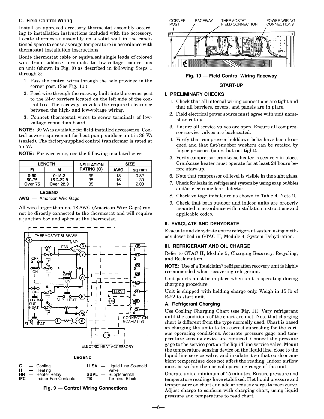
Install an approved accessory thermostat assembly accord- ing to installation instructions included with the accessory. Locate thermostat assembly on a solid wall in the condi- tioned space to sense average temperature in accordance with thermostat installation instructions.

Route thermostat cable or equivalent single leads of colored wire from subbase terminals to low-voltage connections on unit (shown in Fig. 9) as described in following Steps 1 through 3:

1.Pass the control wires through the hole provided in the corner post. (See Fig. 10.)

2.Feed wire through the raceway built into the corner post to the 24-v barriers located on the left side of the con- trol box. The raceway provides the required clearance between the high- and low-voltage wiring.

3.Connect thermostat wires to screw terminals of low- voltage connection board.

NOTE: 39 VA is available for ®eld-installed accessories. Con- trol power requirement for heat pump outdoor unit is 36 VA (sealed). The factory-supplied control transformer is rated at 75 VA.

NOTE: For wire runs, use the following insulated wire:

LENGTH

INSULATION


SIZE

Ft

M

RATING (C)

AWG


sq mm

0-50

0-15.2

35

18


0.82

50-75

15.2-22.9

35

16


1.30

Over 75

Over 22.9

35

14


2.08

LEGEND

AWG Ð American Wire Gage

CORNER

RACEWAY

THERMOSTAT


POWER WIRING

POST


FIELD CONNECTION


CONNECTIONS


Fig. 10 Ð Field Control Wiring Raceway

START-UP

I.PRELIMINARY CHECKS

1.Check that all internal wiring connections are tight and that all barriers, covers, and panels are in place.

2.Field electrical power source must agree with unit name- plate rating.

3.Ensure all service valves are open. Ensure all compres- sor service valves are backseated.

4.Verify that compressor holddown bolts have been loos- ened and that ¯at/snubber washers can be rotated by ®nger pressure (snug, but not tight).

5.Verify compressor crankcase heater is securely in place. Crankcase heater must operate for at least 24 hours be- fore start-up.

6.Note that compressor oil level is visible in the sight glass.

7.Check for leaks in refrigerant system by using soap bubbles and/or electronic leak detector.

8.Check voltage imbalance as shown in Table 4, Note 2.

All wire larger than no. 18 AWG (American Wire Gage) can- not be directly connected to the thermostat and will require a junction box and splice at the thermostat.

9.Check that both outdoor and indoor units are properly mounted in accordance with installation instructions and applicable codes.


LEGEND


C

Ð Cooling

LLSV

Ð Liquid Line Solenoid

H

Ð Heating


Valve

HR

Ð Heater Relay

SUPL Ð Supplemental

IFC Ð Indoor Fan Contactor

TB

Ð Terminal Block

Fig. 9 Ð Control Wiring Connections

II. EVACUATE AND DEHYDRATE

Evacuate and dehydrate entire refrigerant system using meth- ods described in GTAC II, Module 4, System Dehydration.

III. REFRIGERANT AND OIL CHARGE

Refer to GTAC II, Module 5, Charging Recovery, Recycling, and Reclamation.

NOTE: Use of a Totalclaim refrigeration recovery unit is highly recommended when recovering refrigerant.

Unit panels must be in place when unit is operating during charging procedure.

Unit is shipped with holding charge only. Weigh in 15 lb of R-22 to start unit.

A. Refrigerant Charging

Use Cooling Charging Chart (see Fig. 11). Vary refrigerant until the conditions of the chart are met. Note that charging chart is different from the type normally used. Chart is based on charging the units to the correct subcooling for the vari- ous operating conditions. Accurate pressure gage and tem- perature sensing device are required. Connect the pressure gage to the service port on the liquid line service valve. Mount the temperature sensing device on the liquid line, close to the liquid line service valve, and insulate it so that outdoor am- bient temperature does not affect the reading. Indoor air¯ow must be within the normal operating range of the unit.

Operate unit a minimum of 15 minutes. Ensure pressure and temperature readings have stabilized. Plot liquid pressure and temperature on chart and add or reduce charge to meet curve. Adjust charge to conform with charging chart, using liquid pressure and temperature to read chart.

Ð8Ð

Page 8
Image 8
Bryant 575A Field Control Wiring, START-UP Preliminary Checks, II. Evacuate and Dehydrate, III. Refrigerant and OIL Charge

575A specifications

The Bryant 575A is a prominent model in Bryant's lineup of heating, ventilation, and air conditioning (HVAC) systems, known for its reliability and efficiency. Designed with advanced technologies and innovative features, the Bryant 575A is an excellent choice for both residential and light commercial applications.

One of the standout features of the Bryant 575A is its impressive energy efficiency. With a Seasonal Energy Efficiency Ratio (SEER) rating that significantly surpasses the minimum standards, the 575A helps homeowners reduce their energy bills while maintaining optimal comfort levels. The system employs variable-speed technology, allowing for precise temperature control and enhanced humidity management. This ensures that the indoor environment remains comfortable year-round, regardless of outdoor conditions.

Incorporating advanced refrigerant management, the Bryant 575A utilizes environmentally friendly R-410A refrigerant. This refrigerant not only minimizes ozone depletion potential but also enhances the overall performance of the system, allowing for efficient heat exchange and quick temperature adjustments. The system's efficiency is further optimized by its multi-stage cooling capabilities, which allow it to adapt to varying cooling loads and maintain consistent indoor temperatures.

The Bryant 575A is built with reliability in mind, featuring durable construction and quality components designed to withstand the rigors of daily use. Its compact design makes it easy to install in various settings, and its low profile ensures it can fit into tight spaces without compromising performance. Additionally, the system is designed for quiet operation, making it an ideal choice for residential areas where noise may be a concern.

Another significant aspect of the Bryant 575A is its compatibility with Bryant's intelligent thermostat technology. The system can seamlessly integrate with smart home setups, allowing homeowners to control their HVAC systems remotely via smartphone apps or home automation systems. This convenience not only enhances user experience but also contributes to energy savings by allowing for more precise control over heating and cooling schedules.

In summary, the Bryant 575A embodies the blend of efficiency, reliability, and advanced technology, making it a top choice for those seeking a high-performance HVAC solution. With features designed to optimize comfort and energy use, the Bryant 575A stands out as a strong contender in the competitive HVAC market.