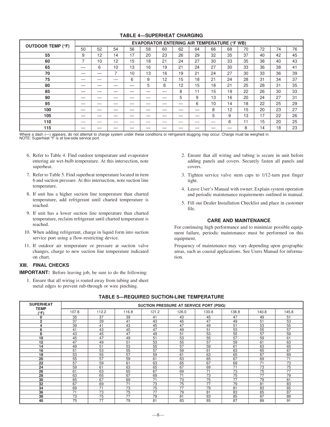
TABLE 4—SUPERHEAT CHARGING

OUTDOOR TEMP (°F)


EVAPORATOR ENTERING AIR TEMPERATURE (°F WB)


50

52

54

56


58


60


62


64


66


68

70


72

74


76


55

9

12

14

17


20


23


26


29


32


35

37


40

42


45

60

7

10

12

15


18


21


24


27


30


33

35


38

40


43

65

6

10

13


16


19


21


24


27


30

33


36

38


41

70

7

10


13


16


19


21


24

27

30


33

36


39

75

6


9


12


15


18


21

24

28


31

34


37

80

5


8

12

15

18

21

25

28

31

35

85

8

11


15


19


22

26


30

33


90

5

9


13


16


20

24


27

31


95


6

10


14


18

22


25

29


100


8


12


15

20


23

27


105


5


9


13

17


22

26


110


6


11

15


20

25


115


8

14


18

23


Where a dash (—) appears, do not attempt to charge system under these conditions or refrigerant slugging may occur. Charge must be weighed in. NOTE: Superheat °F is at low-side service port.

6.Refer to Table 4. Find outdoor temperature and evaporator entering air wet-bulb temperature. At this intersection, note superheat.

7.Refer to Table 5. Find superheat temperature located in item 6 and suction pressure. At this intersection, note suction line temperature.

8.If unit has a higher suction line temperature than charted temperature, add refrigerant until charted temperature is reached.

9.If unit has a lower suction line temperature than charted temperature, reclaim refrigerant until charted temperature is reached.

10.When adding refrigerant, charge in liquid form into suction service port using a flow-restricting device.

11.If outdoor air temperature or pressure at suction valve changes, charge to new suction line temperature indicated on chart.

XIII. FINAL CHECKS

IMPORTANT: Before leaving job, be sure to do the following:

1.Ensure that all wiring is routed away from tubing and sheet metal edges to prevent rub-through or wire pinching.

2.Ensure that all wiring and tubing is secure in unit before adding panels and covers. Securely fasten all panels and covers.

3.Tighten service valve stem caps to 1/12-turn past finger tight.

4.Leave User’s Manual with owner. Explain system operation and periodic maintenance requirements outlined in manual.

5.Fill out Dealer Installation Checklist and place in customer file.

CARE AND MAINTENANCE

For continuing high performance and to minimize possible equip- ment failure, periodic maintenance must be performed on this equipment.

Frequency of maintenance may vary depending upon geographic areas, such as coastal applications. See Users Manual for informa- tion.

TABLE 5—REQUIRED SUCTION-LINE TEMPERATURE

SUPERHEAT


SUCTION PRESSURE AT SERVICE PORT (PSIG)


TEMP


107.8

112.2

116.8


121.2

126.0

130.8


138.8

140.8

145.8

(°F)


0

35

37

39


41

43

45


47

49

51

2

37

39

41


43

45

47


49

51

53

4

39

41

43


45

47

49


51

53

55

6

41

43

45


47

49

51


53

55

57

8

43

45

47


49

51

53


55

57

59

10

45

47

49


51

53

55


57

59

61

12

47

49

51


53

55

57


59

61

63

14

49

51

53


55

57

59


61

63

65

16

51

53

55


57

59

61


63

65

67

18

53

55

57


59

61

63


65

67

69

20

55

57

59


61

63

65


67

69

71

22

57

59

61


63

65

67


69

71

73

24

59

61

63


65

67

69


71

73

75

26

61

63

65


67

69

71


73

75

77

28

63

65

67


69

71

73


75

77

79

30

65

67

69


71

73

75


77

79

81

32

67

69

71


73

75

77


79

81

83

34

69

71

73


75

77

79


81

83

85

36

71

73

75


77

79

81


83

85

87

38

73

75

77


79

81

83


85

87

89

40

75

77

79


81

83

85


87

89

91

—8—

Page 8
Image 8
Bryant 591B Superheat Charging, XIII. Final Checks, Care and Maintenance, Required SUCTION-LINE Temperature

591B specifications

The Bryant 591B is a high-efficiency gas furnace designed to deliver comfort, reliability, and energy savings to homeowners. It stands out in the market for its advanced features and innovative technologies, making it a preferred choice for many.

One of the key features of the Bryant 591B is its two-stage heating capability. This technology allows the furnace to operate at a lower capacity during milder conditions, leading to improved fuel efficiency and consistent comfort levels. When the temperature drops significantly, the furnace shifts to its higher capacity, ensuring your home remains warm and cozy even in extreme weather.

The furnace is equipped with a variable-speed blower motor. This advanced motor allows for quieter operation and enhanced airflow throughout the home. With the ability to adjust speed based on the heating requirements, it not only contributes to better temperature consistency but also improves indoor air quality by facilitating increased filtration cycles.

In terms of energy efficiency, the Bryant 591B has impressive AFUE (Annual Fuel Utilization Efficiency) ratings, which can reach up to 95%. This translates to substantial savings on energy bills, making it an eco-friendly choice as well. The higher the AFUE rating, the more efficient the furnace is at converting fuel into heat, and Bryant has engineered this unit to perform at the top of its class.

Another significant characteristic is the furnace's compatibility with the Bryant Housewise thermostat. This smart thermostat provides users with enhanced control over their home heating, allowing for customized scheduling and remote access. This technology helps optimize energy usage while maintaining comfort, ensuring that you only heat your space when needed.

Additionally, the 591B is designed with a durable cabinet that minimizes noise and enhances performance. Insulated for sound, this furnace operates quietly in the background without disrupting daily life. Furthermore, its compact design allows for ease of installation in tight spaces, making it suitable for various home configurations.

Overall, the Bryant 591B offers a blend of efficiency, technology, and innovative features. Its two-stage heating, variable-speed blower motor, high AFUE ratings, and compatibility with smart thermostats provide both homeowners and contractors with an advanced heating solution that prioritizes comfort, efficiency, and user convenience. With the Bryant 591B, you can expect reliable warmth throughout the winter months while enjoying lower energy costs and a decreased environmental footprint.