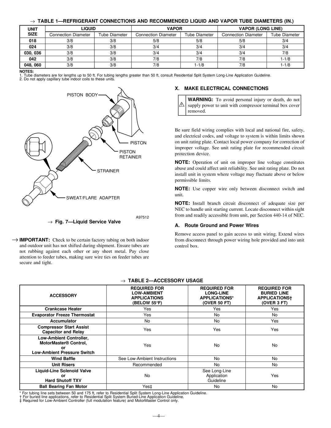
TABLE 1ÐREFRIGERANT CONNECTIONS AND RECOMMENDED LIQUID AND VAPOR TUBE DIAMETERS (IN.)

UNIT

LIQUID


VAPOR


VAPOR (LONG LINE)

SIZE

Connection Diameter


Tube Diameter

Connection Diameter


Tube Diameter

Connection Diameter

Tube Diameter


018

3/8


3/8

5/8


5/8

5/8

3/4

024

3/8


3/8

3/4


3/4

3/4

3/4

030, 036

3/8


3/8

3/4


3/4

3/4

7/8

042

3/8


3/8

7/8


7/8

7/8

1-1/8

048, 060

3/8


3/8

7/8


1-1/8

7/8

1-1/8


NOTES:

1.Tube diameters are for lengths up to 50 ft. For tubing lengths greater than 50 ft, consult Residential Split System Long-Line Application Guideline.

2.Do not apply capillary tube indoor coils to these units.

PISTON BODY

PISTON

PISTON

RETAINER

X.MAKE ELECTRICAL CONNECTIONS

WARNING: To avoid personal injury or death, do not supply power to unit with compressor terminal box cover removed.

Be sure field wiring complies with local and national fire, safety, and electrical codes, and voltage to system is within limits shown on unit rating plate. Contact local power company for correction of improper voltage. See unit rating plate for recommended circuit protection device.

STRAINER

SWEAT/FLARE ADAPTER

Fig. 7ÐLiquid Service Valve

A97512

NOTE: Operation of unit on improper line voltage constitutes abuse and could affect unit reliability. See unit rating plate. Do not install unit in system where voltage may fluctuate above or below permissible limits.

NOTE: Use copper wire only between disconnect switch and unit.

NOTE: Install branch circuit disconnect of adequate size per NEC to handle unit starting current. Locate disconnect within sight from and readily accessible from unit, per Section 440-14 of NEC.

A.Route Ground and Power Wires

IMPORTANT: Check to be certain factory tubing on both indoor and outdoor unit has not shifted during shipment. Ensure tubes are not rubbing against each other or any sheet metal. Pay close attention to feeder tubes, making sure wire ties on feeder tubes are secure and tight.

Remove access panel to gain access to unit wiring. Extend wires from disconnect through power wiring hole provided and into unit control box.

TABLE 2ÐACCESSORY USAGE


REQUIRED FOR

REQUIRED FOR

REQUIRED FOR

ACCESSORY

LOW-AMBIENT

LONG-LINE

BURIED LINE

APPLICATIONS

APPLICATIONS*

APPLICATIONS²


(BELOW 55°F)

(OVER 50 FT)

(OVER 3 FT)

Crankcase Heater

Yes

Yes

Yes

Evaporator Freeze Thermostat

Yes

No

No

Accumulator

No

No

Yes

Compressor Start Assist

Yes

Yes

Yes

Capacitor and Relay


Low-Ambient Controller,


MotorMaster® Control,

Yes

No

No

or


Low-Ambient Pressure Switch


Wind Baffle

See Low-Ambient Instructions

No

No

Unit Risers

Recommended

No

No

Liquid-Line Solenoid Valve


See Long-Line


or

No

Application

Yes

Hard Shutoff TXV


Guideline


Ball Bearing Fan Motor

Yes³

No

No

*For tubing line sets between 50 and 175 ft, refer to Residential Split System Long-Line Application Guideline. ² For buried line applications, refer to Residential Split System Buried-Line Application Guideline.

³ Required for Low-Ambient Controller (full modulation feature) and MotorMaster Control only.

Ð4Ð

Page 4
Image 4
Bryant 663C Make Electrical Connections, → ÐLiquid Service Valve, Route Ground and Power Wires, → Ðaccessory Usage, Ð4Ð

663C specifications

The Bryant 663C is a high-efficiency gas furnace designed to deliver exceptional comfort and reliability in residential heating. As part of the Bryant lineup, it combines advanced technology with durable construction, ensuring homeowners can enjoy warmth during the coldest months while also being energy-efficient.

One of the standout features of the Bryant 663C is its impressive Annual Fuel Utilization Efficiency (AFUE) rating. With an AFUE of up to 96%, this furnace is designed to convert a significant portion of the fuel it consumes into usable heat, thus minimizing energy waste. This high-efficiency rating not only translates into lower utility bills but also has a positive impact on the environment.

The 663C is equipped with a two-stage heating system, which allows it to operate at different levels of output depending on the heating demand. This functionality provides enhanced comfort by eliminating temperature swings and maintaining a consistent indoor environment. In addition, the variable-speed blower motor adjusts the airflow based on the heating requirements, further optimizing efficiency and comfort.

Comfort and convenience are paramount in the design of the Bryant 663C. Its compatibility with Bryant's Wi-Fi-enabled smart thermostats allows homeowners to control their heating system remotely, providing ease of access and energy savings. The integration of advanced technology extends to its quiet operation; the unit is designed to minimize sound, ensuring that heating does not disrupt the peaceful ambiance of the home.

Durability is another critical aspect of the Bryant 663C. Constructed with a stainless steel heat exchanger, this furnace not only ensures optimal heat transfer but also resists corrosion, enhancing its lifespan. In addition, the inclusion of a durable cabinet and a heavy-duty blower motor offers further protection and reliability, making it a long-lasting investment for any homeowner.

Overall, the Bryant 663C stands out in the competitive market of heating systems due to its impressive efficiency, advanced features, and a commitment to comfort and longevity. Whether for new constructions or retrofitting an existing home, the 663C is an excellent choice for those seeking a reliable and energy-efficient gas furnace.