C. Unit Controls

Compressor

High-Pressure Relief Valve Ð Valve is located in compressor. Relief valve opens at a pressure differential of approximately 450 psi between suction (low side) and discharge (high side) to allow pressure equalization.

Internal Current and Temperature Sensing Overload Ð Device resets automatically when internal compressor motor temperature drops to a safe level. When an internal overload is suspected of being open, check by using an ohmmeter or continuity tester.

D. Cooling Sequence of Operation

NOTE: With the FAN switch in the ON position, 24 v is sup- plied to the time-delay relay (TDR) through the G terminal on the thermostat. This voltage energizes the coil of the re- lay, closing the normally-open set of contacts which provide continuous power to the indoor (evaporator) fan motor (IFM). Moving the FAN switch back to the AUTO. position (provid- ing there is not a call for cooling) deenergizes the TDR (when applicable) which deenergizes the IFM after a 30-second de- lay. The FAN switch in AUTO. position cycles upon a call for cooling.

On a call for cooling, 24 v is supplied to the compressor con- tactor (C) and TDR simultaneously through the Y and G ter- minals of the thermostat, respectively. On units with a com- pressor TDR, there is a built-in, 5-minute (±45 seconds) delay between compressor starts. Energizing the contactor closes the normally-open set of contacts supplying power to both the compressor and outdoor (condenser) fan motor (OFM). Ener- gizing the TDR closes the normally-open set of contacts pro- viding power to the IFM. On the loss of the call for cooling, 24 v is removed from both the Y and G terminals of the ther- mostat (providing the FAN switch is in the AUTO. position), deenergizing both the compressor and TDR and opening both the contacts supplying power to compressor and OFM. IFM has a 30-second delay.

III. INDOOR AIRFLOW AND AIRFLOW ADJUSTMENTS

CAUTION: For cooling operation, the recommended air¯ow is 350 to 450 cfm per each 12,000 Btuh of rated cooling capacity.

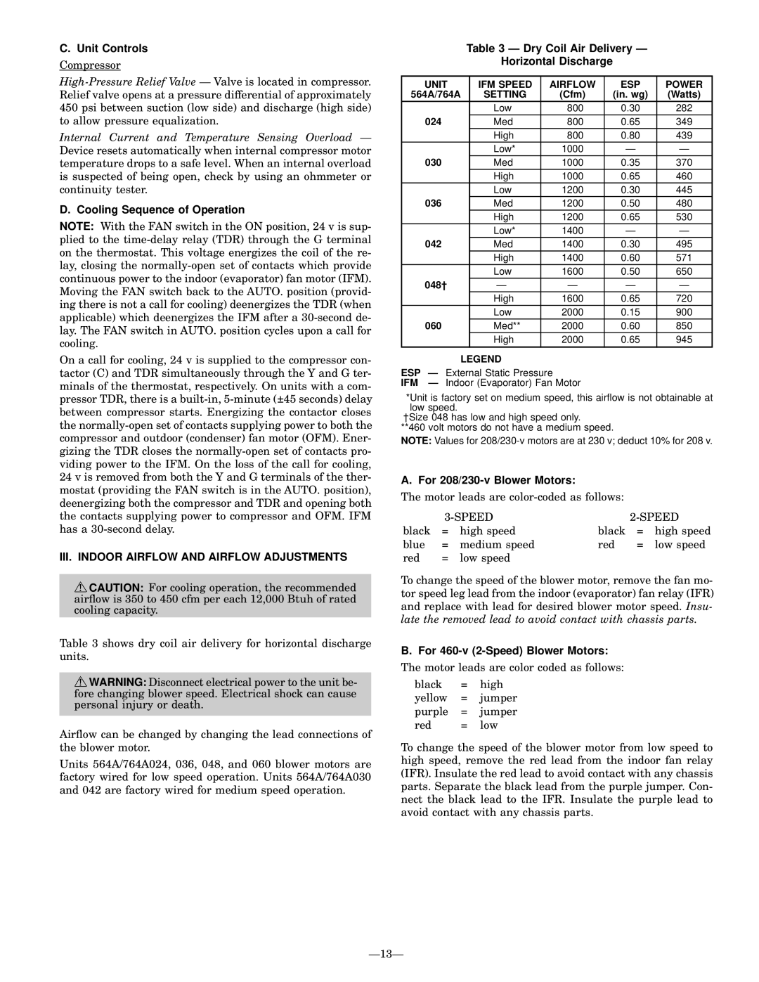
Table 3 shows dry coil air delivery for horizontal discharge units.

WARNING: Disconnect electrical power to the unit be- fore changing blower speed. Electrical shock can cause personal injury or death.

Air¯ow can be changed by changing the lead connections of the blower motor.

Units 564A/764A024, 036, 048, and 060 blower motors are factory wired for low speed operation. Units 564A/764A030 and 042 are factory wired for medium speed operation.

Table 3 Ð Dry Coil Air Delivery Ð

Horizontal Discharge

UNIT

IFM SPEED

AIRFLOW

ESP

POWER

564A/764A

SETTING

(Cfm)

(in. wg)

(Watts)


Low

800

0.30

282

024

Med

800

0.65

349


High

800

0.80

439


Low*

1000

Ð

Ð

030

Med

1000

0.35

370


High

1000

0.65

460


Low

1200

0.30

445

036

Med

1200

0.50

480


High

1200

0.65

530


Low*

1400

Ð

Ð

042

Med

1400

0.30

495


High

1400

0.60

571


Low

1600

0.50

650

048²

Ð

Ð

Ð

Ð


High

1600

0.65

720


Low

2000

0.15

900

060

Med**

2000

0.60

850


High

2000

0.65

945


LEGEND

ESP Ð External Static Pressure

IFM Ð Indoor (Evaporator) Fan Motor

*Unit is factory set on medium speed, this air¯ow is not obtainable at low speed.

²Size 048 has low and high speed only.

**460 volt motors do not have a medium speed.

NOTE: Values for 208/230-v motors are at 230 v; deduct 10% for 208 v.

A. For 208/230-v Blower Motors:

The motor leads are color-coded as follows:


3-SPEED


2-SPEED

black

=

high speed

black

=

high speed

blue

=

medium speed

red

=

low speed

red

=

low speed


To change the speed of the blower motor, remove the fan mo- tor speed leg lead from the indoor (evaporator) fan relay (IFR) and replace with lead for desired blower motor speed. Insu- late the removed lead to avoid contact with chassis parts.

B. For 460-v (2-Speed) Blower Motors:

The motor leads are color coded as follows:

black

=

high

yellow

=

jumper

purple

=

jumper

red

=

low

To change the speed of the blower motor from low speed to high speed, remove the red lead from the indoor fan relay (IFR). Insulate the red lead to avoid contact with any chassis parts. Separate the black lead from the purple jumper. Con- nect the black lead to the IFR. Insulate the purple lead to avoid contact with any chassis parts.

Ð13Ð

Page 13
Image 13
Bryant 764A installation instructions III. Indoor Airflow and Airflow Adjustments

764A specifications

The Bryant 764A is a high-performance air conditioning and heating system that exemplifies efficiency and reliability for residential and commercial use. Designed to deliver optimal comfort in various climates, the 764A is known for its impressive energy efficiency ratings and advanced technologies.

One of the standout features of the Bryant 764A is its variable speed compressor. This innovative component allows the system to adjust its output according to the specific cooling or heating demands of the environment. By operating at different speeds, the compressor can maintain a consistent indoor temperature while using less energy compared to traditional single-stage systems. This not only enhances comfort but also contributes to significant energy savings over time.

The Bryant 764A is equipped with a smart thermostat that offers precise control over indoor climates. This thermostat can be programmed to adjust temperatures based on user preferences and schedules, further improving energy efficiency. Users can also control the system remotely via a smartphone app, ensuring comfort is just a tap away.

In terms of its construction, the Bryant 764A is built with durability in mind. The unit features a robust cabinet designed to withstand harsh weather conditions, which extends the lifespan of the system. Additionally, its sound-dampening technology minimizes operational noise, creating a more peaceful indoor environment.

The 764A incorporates advanced filtration systems to improve indoor air quality. With allergen filtration capabilities, it effectively reduces dust, pollen, and other airborne particles, making it an excellent choice for allergy sufferers. This focus on air quality aligns with Bryant's commitment to creating healthier living spaces.

Moreover, the Bryant 764A is designed with environmentally friendly refrigerants, aligning with modern standards for reducing greenhouse gas emissions. This commitment to sustainability is becoming increasingly important for consumers looking to reduce their environmental footprint.

Overall, the Bryant 764A stands out as a comprehensive solution for heating and cooling needs. With its variable speed technology, smart thermostat, durable construction, and focus on air quality, it offers both efficiency and comfort, making it a wise investment for any property owner looking to enhance their indoor environment.