Burnham 81433101R16-1/10 manual III. Water Piping and Trim

Models: 81433101R16-1/10

1 40
Download 40 pages 18.46 Kb
Page 9
Image 9

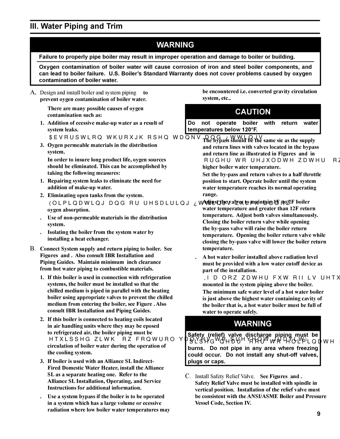
III. Water Piping and Trim

WARNING

Failure to properly pipe boiler may result in improper operation and damage to boiler or building.

Oxygen contamination of boiler water will cause corrosion of iron and steel boiler components, and can lead to boiler failure. U.S. Boiler’s Standard Warranty does not cover problems caused by oxygen contamination of boiler water.

A. Design and install boiler and system piping to prevent oxygen contamination of boiler water.

There are many possible causes of oxygen contamination such as:

1.Addition of excessive make-up water as a result of system leaks.

2.Absorption through open tanks and fittings.

3.Oxygen permeable materials in the distribution system.

In order to insure long product life, oxygen sources should be eliminated. This can be accomplished by taking the following measures:

1.Repairing system leaks to eliminate the need for addition of make-up water.

2.Eliminating open tanks from the system.

3.Eliminating and/or repairing fittings which allow oxygen absorption.

4.Use of non-permeable materials in the distribution system.

5.Isolating the boiler from the system water by installing a heat exchanger.

B.Connect System supply and return piping to boiler. See Figures 5 and 7. Also consult I=B=R Installation and Piping Guides. Maintain minimum ½ inch clearance from hot water piping to combustible materials.

be encountered (i.e. converted gravity circulation system, etc.).

CAUTION

Do not operate boiler with return water temperatures below 120°F.

The bypass should be the same size as the supply and return lines with valves located in the bypass and return line as illustrated in Figures 5 and 7 in order to regulate water flow for maintenance of higher boiler water temperature.

Set the by-pass and return valves to a half throttle position to start. Operate boiler until the system water temperature reaches its normal operating range.

Adjust the valves to maintain 180°F to 200°F boiler water temperature and greater than 120°F return temperature. Adjust both valves simultaneously. Closing the boiler return valve while opening

the by-pass valve will raise the boiler return temperature. Opening the boiler return valve while closing the by-pass valve will lower the boiler return temperature.

5.A hot water boiler installed above radiation level must be provided with a low water cutoff device as part of the installation.

1.If this boiler is used in connection with refrigeration systems, the boiler must be installed so that the chilled medium is piped in parallel with the heating boiler using appropriate valves to prevent the chilled medium from entering the boiler, see Figure 6. Also consult I=B=R Installation and Piping Guides.

2.If this boiler is connected to heating coils located in air handling units where they may be exposed to refrigerated air, the boiler piping must be equipped with flow control valves to prevent gravity circulation of boiler water during the operation of the cooling system.

3.If boiler is used with an Alliance™ SL Indirect- Fired Domestic Water Heater, install the Alliance™ SL as a separate heating zone. Refer to the Alliance™ SL Installation, Operating, and Service Instructions for additional information.

4.Use a system bypass if the boiler is to be operated in a system which has a large volume or excessive radiation where low boiler water temperatures may

If a low water cut-off is required, it must be mounted in the system piping above the boiler.

The minimum safe water level of a hot water boiler is just above the highest water containing cavity of the boiler; that is, a hot water boiler must be full of water to operate safely.

WARNING

Safety (relief) valve discharge piping must be piped near floor to eliminate potential of severe burns. Do not pipe in any area where freezing could occur. Do not install any shut-off valves, plugs or caps.

C.Install Safety Relief Valve. See Figures 5 and 7. Safety Relief Valve must be installed with spindle in vertical position. Installation of the relief valve must be consistent with the ANSI/ASME Boiler and Pressure Vessel Code, Section IV.


Page 9
Image 9
Burnham 81433101R16-1/10 manual III. Water Piping and Trim

81433101R16-1/10 specifications

The Burnham 81433101R16-1/10 is a highly regarded component within the realm of heating, ventilation, and air conditioning (HVAC) systems, known for its reliability and performance. This specific part is designed to enhance the efficiency of heating systems, making it an essential component for both residential and commercial applications.

One of the standout features of the Burnham 81433101R16-1/10 is its durable construction. Made with high-quality materials, this product is built to withstand the rigors of continuous operation in various environmental conditions. Its robust design ensures a longer lifespan, reducing the need for frequent replacements and maintenance, which ultimately saves on operational costs.

The Burnham 81433101R16-1/10 incorporates advanced technology to optimize energy usage. This part is engineered for high efficiency, meaning that it works to convert a maximum amount of energy into heat with minimal waste. The integration of cutting-edge technology ensures that users experience significant energy savings, which not only helps in reducing utility bills but also contributes positively to environmental sustainability.

In terms of compatibility, the Burnham 81433101R16-1/10 is designed to work seamlessly with various heating systems. This makes it a versatile choice for technicians and homeowners alike, as it can be easily integrated without extensive modifications. The ease of installation is another appealing characteristic, allowing for quicker setups that minimize downtime.

Furthermore, this component prioritizes safety, featuring built-in mechanisms that help prevent overheating and other potential hazards. This focus on safety reassures users that their heating systems can operate efficiently without compromising the well-being of their households or properties.

The Burnham 81433101R16-1/10 is also known for its user-friendly design. Technicians find that maintenance and inspection processes are straightforward, allowing for easy access to components for troubleshooting or routine checks. This practical feature enhances user satisfaction and simplifies operational management.

Overall, the Burnham 81433101R16-1/10 exemplifies a commitment to quality, efficiency, and safety in HVAC applications. Its combination of durability, advanced technology, and versatile compatibility makes it a valuable choice for anyone looking to enhance their heating system's performance. By opting for the Burnham 81433101R16-1/10, users can enjoy efficient heating solutions that meet their needs for comfort and energy conservation.