III. Operating Instructions

Safe lighting and other performance criteria were met with the gas manifold and control assembly provided on the boiler when the boiler underwent tests specified in ANSI Z21.13.

1INSPECT INSTALLATION BEFORE STARTING.

2INITIAL START

a.FILL ENTIRE HEATING SYSTEM WITH WATER and vent air from system. Vent air from all heat distributing units and all high points in the piping of the system. When venting air from system keep fill valve in open position to maintain water pressure. Make certain pressure reducing valve is installed between the fill valve and the boiler. (See Figure 7)

Use the following procedure on a series loop system equipped with zone valves.

1. Close all but one zone valve.

c.Be sure that gas to pilot and main burners has been off for at least five minutes.

d.Open valve on main gas line at meter.

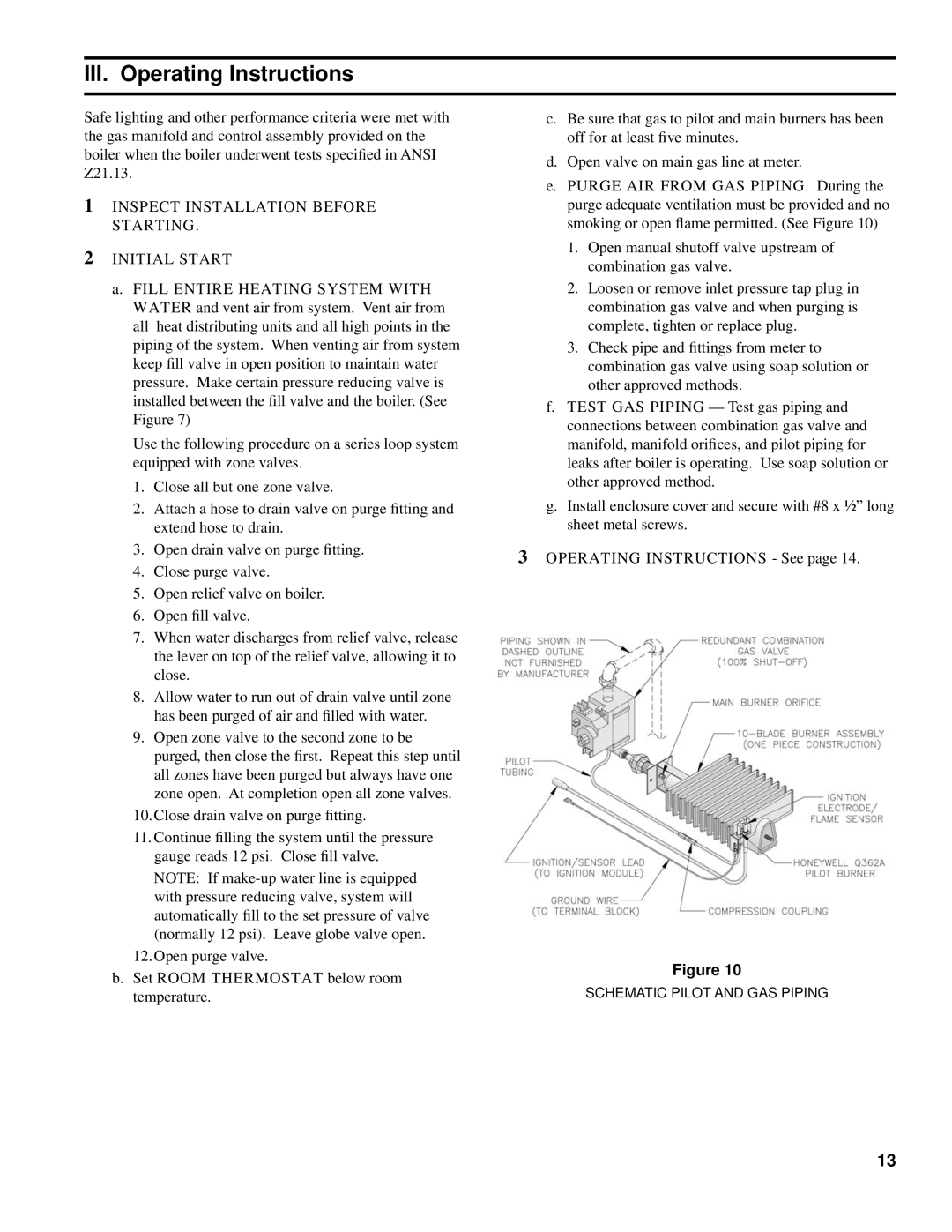
e.PURGE AIR FROM GAS PIPING. During the purge adequate ventilation must be provided and no smoking or open flame permitted. (See Figure 10)

1.Open manual shutoff valve upstream of combination gas valve.

2.Loosen or remove inlet pressure tap plug in combination gas valve and when purging is complete, tighten or replace plug.

3.Check pipe and fittings from meter to combination gas valve using soap solution or other approved methods.

f.TEST GAS PIPING — Test gas piping and connections between combination gas valve and manifold, manifold orifices, and pilot piping for leaks after boiler is operating. Use soap solution or other approved method.

2.

Attach a hose to drain valve on purge fitting and

g. Install enclosure cover and secure with #8 x ½” long


extend hose to drain.

sheet metal screws.

3.

Open drain valve on purge fitting.

3 OPERATING INSTRUCTIONS - See page 14.

4.

Close purge valve.


5.

Open relief valve on boiler.


6.

Open fill valve.


7.

When water discharges from relief valve, release


the lever on top of the relief valve, allowing it to


close.


8.

Allow water to run out of drain valve until zone


has been purged of air and filled with water.


9.

Open zone valve to the second zone to be


purged, then close the first. Repeat this step until


all zones have been purged but always have one


zone open. At completion open all zone valves.


10.Close drain valve on purge fitting.


11. Continue filling the system until the pressure


gauge reads 12 psi. Close fill valve.


NOTE: If make-up water line is equipped


with pressure reducing valve, system will


automatically fill to the set pressure of valve


(normally 12 psi). Leave globe valve open.


12.Open purge valve.

b. Set ROOM THERMOSTAT below room

Figure 10

SCHEMATIC PILOT AND GAS PIPING

temperature.

13

Page 13
Image 13
Burnham SM-6 manual III. Operating Instructions, Inspect Installation Before Starting Initial Start

SM-6 specifications

The Burnham SM-6 is a high-performance modular boiler designed for commercial and industrial applications. Known for its efficiency and reliability, the SM-6 is engineered to meet a wide range of heating demands while maintaining low operational costs.

One of the standout features of the SM-6 is its modular design. This allows for scalable installations, catering to varying heating needs without requiring extensive modifications. The boiler can operate independently or in conjunction with other units, providing flexibility that is essential for industries with fluctuating demands.

In terms of technology, the Burnham SM-6 utilizes advanced combustion technology to achieve high efficiency rates. The unit typically operates with a stellar thermal efficiency of around 85% to 90%, minimizing fuel consumption and reducing greenhouse gas emissions. The incorporation of electronic ignition further helps in conserving energy, as it eliminates the need for a standing pilot light.

The SM-6 is made from high-quality materials designed for durability and long service life. The heat exchanger is constructed with durable steel, enabling it to withstand high temperatures and pressures. This robust construction ensures reliability in demanding environments, mitigating the risk of breakdowns and enhancing overall productivity.

Another key characteristic of the Burnham SM-6 is its user-friendly control system. The boiler is equipped with a state-of-the-art control panel that provides operators with real-time data on performance metrics. This allows for proactive maintenance and performance optimization, enhancing the overall operational efficiency of the system.

Safety is also a paramount consideration in the design of the SM-6. It includes multiple safety features, such as pressure relief valves and electronic safety checks, to prevent dangerous operating conditions. These features ensure that the boiler can run safely over extended periods, providing peace of mind for facility managers.

In conclusion, the Burnham SM-6 boiler stands out in the market for its modular design, high efficiency, durable construction, and advanced control technologies. Its versatile nature makes it an excellent choice for various applications, from manufacturing facilities to commercial buildings, ensuring it meets the heating requirements of diverse industries effectively. The combination of efficiency, reliability, and safety solidifies the Burnham SM-6 as a leading solution in the realm of heating systems.