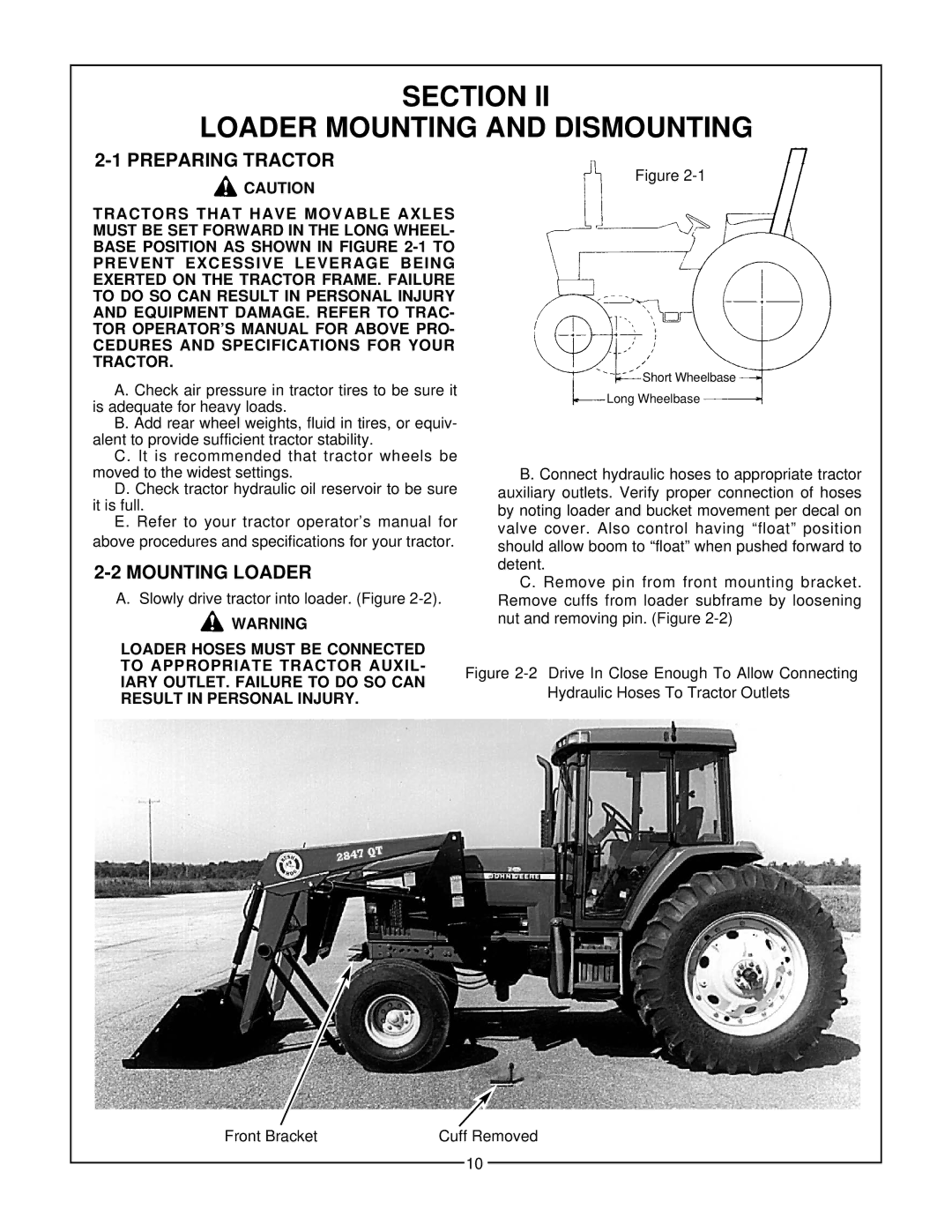
2427, 3227 QT, 2847 specifications
The Bush Hog 2847, 3227 QT, and 2427 are leading models in the category of rotary cutters, designed for demanding agricultural and landscaping tasks. Notably recognized for their robust construction and high performance, each model caters to different scales of operation while ensuring efficiency and reliability.The Bush Hog 2847 is a versatile rotary cutter that offers a cutting width of 84 inches, making it suitable for larger properties and commercial applications. It features a heavy-duty gear drive for enhanced power transfer, which allows for cutting through dense brush and tall grass effortlessly. Equipped with a rugged, reinforced frame, the 2847 stands up to tough working conditions and provides users with a long-lasting tool. Its quick-attach design simplifies mounting and dismounting, improving productivity by minimizing downtime.
Moving to the Bush Hog 3227 QT, often favored for its compact size, this model provides a cutting width of 72 inches. Ideal for both residential and light commercial use, the QT signifies "Quick-Tach," which highlights its easy attachment system. This rotary cutter incorporates a floating top link, allowing for better contour following, ensuring an even cut over undulated terrain. The 3227 is also equipped with heavy-duty blades that enhance cutting efficiency and durability, enabling it to handle a variety of vegetation types with ease.
The Bush Hog 2427 complements the series with a slightly smaller profile, featuring a cutting width of 60 inches. It targets users who need a reliable cutter for smaller jobs or tight spaces. The 2427 is engineered with a solid frame and a unique blade design that ensures optimal cutting performance while preserving the health of the landscape. It also includes a slip clutch or chain driveline option, providing additional protection against shocks from unexpected obstacles during operation.
All three models boast user-friendly technologies such as adjustable cutting heights, ensuring adaptability to varying grass lengths. Their maintenance-friendly designs, with easily accessible grease points and durable materials, contribute to lower upkeep costs over their lifespan. Each rotary cutter in the Bush Hog lineup embodies a blend of power, durability, and innovation, making them essential tools for land management professionals and avid homeowners alike.

