SECTION II
PREPARATION FOR USE
|
|
|
|
| Due to the many variations in trac- | |||
|
|
|
|
|
|
|
| NOTE |
|
|
| WARNING |
|
|
|
| tor/implement hitch points and corre- |
| NEVER STAND BETWEEN TRACTOR |
|
| sponding differences in distances between | ||||
|
|
| tractor PTO shafts and implement input | |||||
| AND CUTTER WHILE TRACTOR IS |
|
| shafts, drivelines may need to be short- | ||||
| BEING BACKED TO HITCH. |
|
|
|
| ened as described in the following steps: | ||
|
|
| WARNING |
|
|
| B. | Raise and lower cutter to determine position |
ADDITIONAL | TRACTOR | FRONT |
| with shortest distance between the tractor PTO shaft | ||||
BALLAST MAY BE NEEDED FOR |
| and gearbox input shaft. Shut down tractor leaving | ||||||
STABLE OPERATION AND TRANSPORT |
| cutter in position of shortest distance. SECURELY | ||||||
OF CUTTER. SEE TRACTOR OPERA- |
| |||||||
TOR’S MANUAL FOR RECOMMENDED |
| BLOCK CUTTER IN POSITION. | ||||||
WEIGHTS. IT IS RECOMMENDED THAT |
| C. Pull driveline apart. Attach outer (female) sec- | ||||||
TRACTOR | BE | EQUIPPED | WITH |
| tion to tractor PTO shaft. Pull on driveline section to | |||
ROLLOVER | PROTECTIVE SYSTEM |
| be sure yoke locks into place. | |||||
(ROPS) AND SEAT BELTS. |
|
|
| D. Hold driveline sections parallel to each other to | ||||
A. Attach to tractor Cat. I three point hitch | as | determine if too long. Each section should end | ||||||
described in tractor operator’s manual. |
|
|
| approximately 3 inches (76mm) short of reaching | ||||
|
|
| universal joint shield on opposite section. If too long, | |||||
|
|
|
|
|
|
| measure 3 inches (76mm) back from universal joint | |
|
|
|
|
|
|
| ||
|
|
|
|
|
|
| shield and mark opposite section. (Figure | |
|
|
|
|
|
|
| this for both sections. | |
|
|
|
|
|
|
| E. Raise and lower cutter to determine position | |
|
|
|
|
|
|
| with greatest distance between PTO shaft and gear- | |
|
|
|
|
|
|
| box input shaft. Shut down tractor leaving cutter in | |
|
|
|
|
|
|
| position of greatest distance. SECURELY BLOCK | |
|
|
|
|
|
|
| CUTTER IN POSITION. | |
|
|
|
|
|
|
| F. Hold down driveline sections parallel to each | |
|
|
|
|
|
|
| other and check for minimum 6 inches (152mm) | |
|
|
|
|
|
|
| overlap. (Figure | |
|
|
|
|
|
|
| cutting, overlap will be the distance between two | |
|
|
|
|
|
|
| marks. If driveline has less than minimum overlap, | |
|
|
|
|
|
|
| DO NOT USE. Contact authorized Bush Hog dealer. | |
|
|
|
|
|
|
|
| NOTE |
|
|
|
|
|
|
| If driveline is correct length, omit the fol- | |
|
|
|
|
|
|
| lowing steps “G” through “J” and proceed | |
|
|
|
|
|
|
| to step “K”. | |
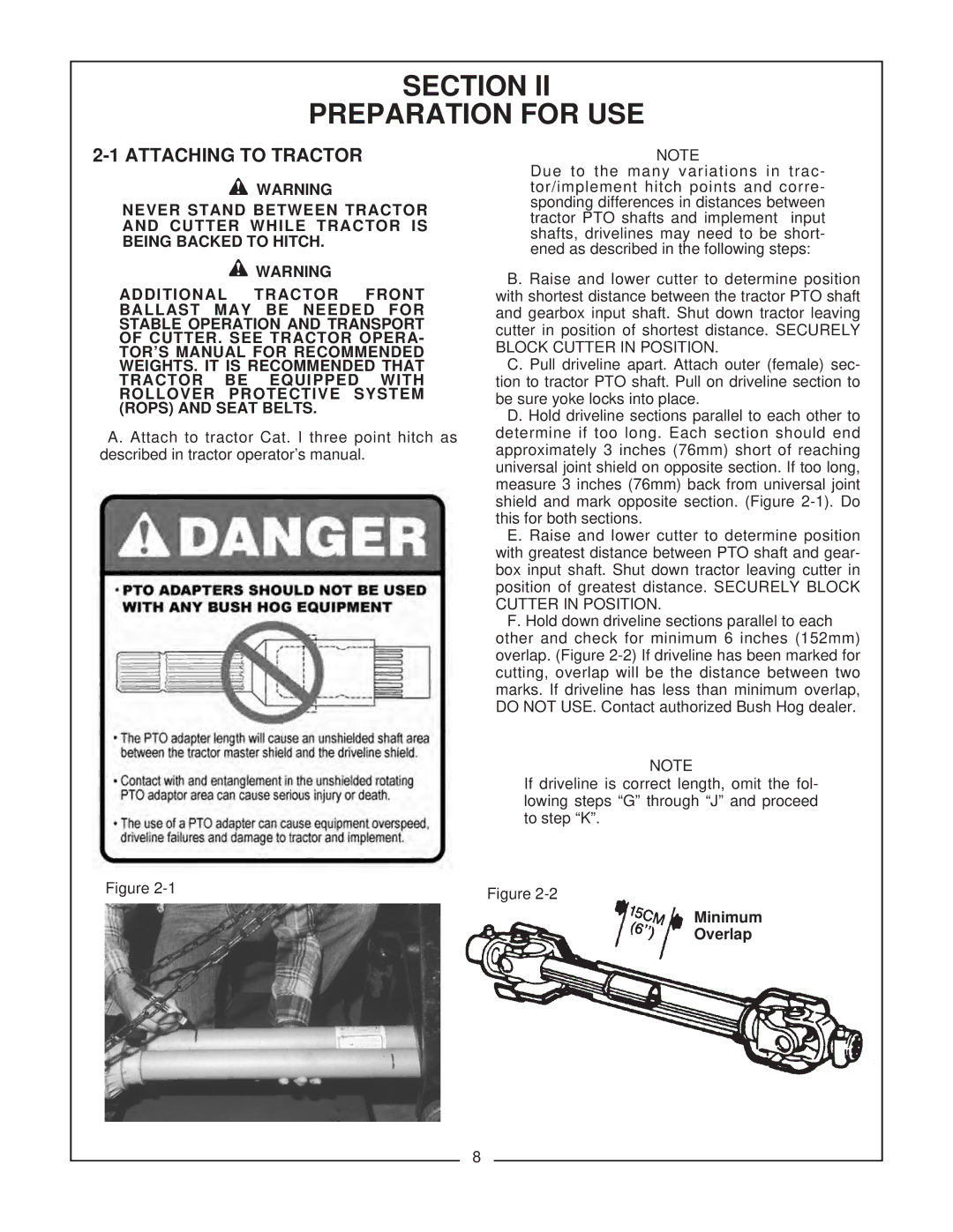
Figure | Figure | Minimum |
| ||
|
| |
|
| Overlap |
8
