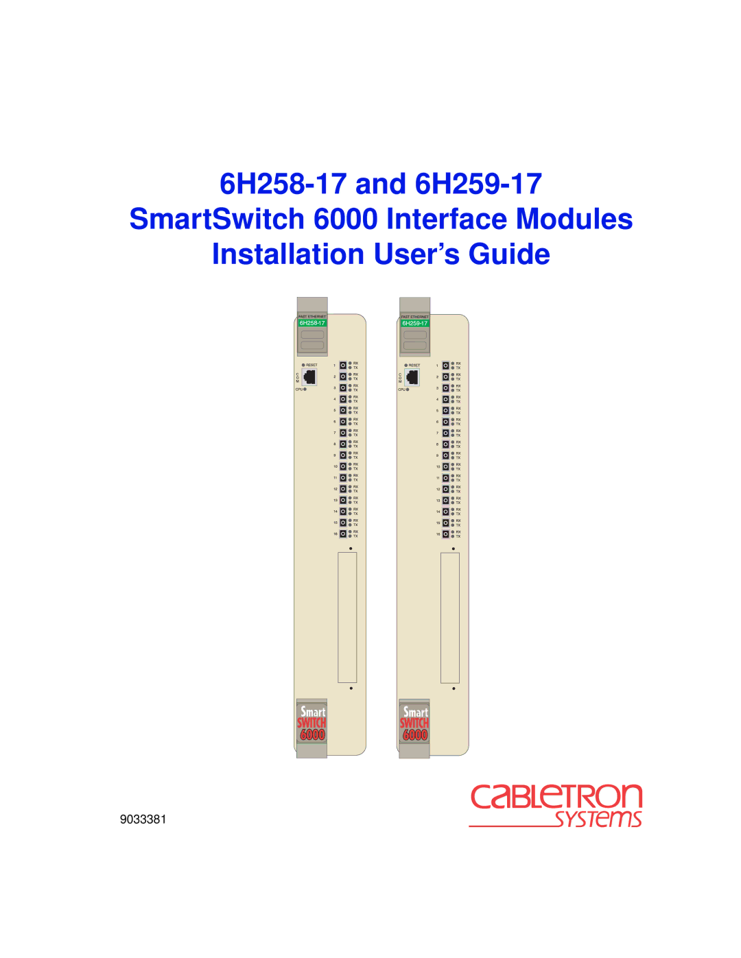
6H259-17, 6H258-17 specifications
Cabletron Systems, a pioneer in computer networking and telecommunications, has consistently delivered innovative solutions tailored to meet the evolving demands of network infrastructure. Among its notable offerings are the models 6H258-17 and 6H259-17, which showcase advanced technological features designed to optimize network performance, reliability, and scalability.The 6H258-17 stands out as a high-performance network switch, boasting 24 Ethernet ports, facilitating efficient data transfer and connectivity among multiple devices. Its architecture supports both 10BASE-T and 100BASE-TX Ethernet standards, providing flexibility in deploying a variety of network configurations. The switch also employs innovative packet-switching technology, ensuring low-latency communication and enhanced throughput, which is critical for bandwidth-intensive applications.
On the other hand, the 6H259-17 acts as a versatile router and works seamlessly with the 6H258-17 switch, creating a cohesive networking solution. This model is equipped with a robust routing protocol suite, including RIP and OSPF, to facilitate intelligent data routing across networks. Its ability to accommodate various WAN interfaces further enhances its adaptability in different networking environments, making it suitable for both small businesses and larger enterprise setups.
One of the key characteristics of both models is their modular design, which allows for easy upgrades and expansions as the networking requirements grow. Users can invest in additional modules or line cards, enabling them to scale their systems without the need for complete replacements. This feature not only extends the lifespan of the equipment but also aligns with cost-effective budgeting strategies.
In terms of security, Cabletron Systems has integrated sophisticated features into both products to safeguard data integrity and prevent unauthorized access. The ability to implement VLANs and access control lists ensures that only authorized users can access sensitive information. This focus on security is paramount in today’s landscape, where data breaches pose significant risks to organizations of all sizes.
Additionally, both the 6H258-17 and 6H259-17 are designed for easy management and monitoring. With a user-friendly interface and support for SNMP, network administrators can efficiently oversee network activities, troubleshoot issues, and optimize performance.
In conclusion, the Cabletron Systems 6H258-17 and 6H259-17 represent powerful networking solutions that combine performance, scalability, security, and ease of management. Their advanced technologies make them a valuable choice for organizations looking to enhance their network infrastructure while ensuring future growth and adaptability.